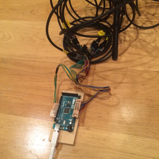
Because toneglow is fully wired, cabling is a large issue, and we wanted to make it so that it can easily be taken apart/put back together. In all of the prototype videos so far, the cables have been directly soldered to the control units on one end and just poked into the breadboard at the other end. This worked, but was obviously far from ideal as seen from this picture of a mess of wires:
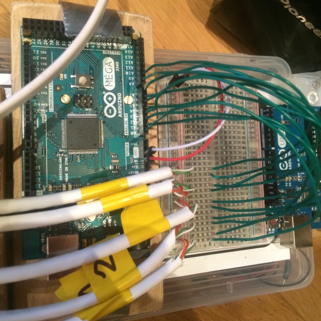
This picture is from when there were no LEDs, so try to imagine 10 more cables going around all over the place precariously.
Ethernet Cables:
We were using ethernet cable to connect all of the units as it has 8 wires inside a reasonably slim frame. This gave us easy room to expand if we wanted to insert more components which would use more cores of the cable. Using ethernet cable was also useful as we could just solder ethernet sockets to the units and to the Arduino. But we realised quite soon that finding female ethernet sockets as a standalone item was quite difficult. We then decided to scour Amazon for ethernet couplers which we thought we could take apart and use the sockets from those. And this is what we came up with.


As the image shows, each coupler has a PCB with two female sockets attached to it. We tried to desolder them from the board but found it to be quite difficult as it was fiddly to get the solder sucker into all the crevices. After trying this for a while we decided just to go the old fashioned brute force way and use a dremel to cut them in half. We ended up with these:
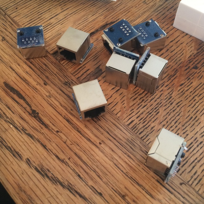
They’re not pretty but they are functional.
Having standardised connections made it a lot easier for us to do wiring, as we could work out which pins were what and just easily connect it that way. This is how we connected the pins:
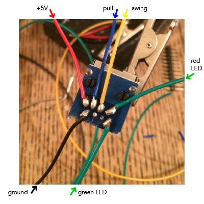
As you can see the soldering was quite fiddly so it was hard not to get a short, but we managed it in the end and ultimately, the addition of these ethernet cables is what makes our project so much more easy to set up and take down.
As a side note, you will notice that the cables used for the LEDs are both green. The one for the red LED is marked at the other end though, so it can be easily differentiated.
Arduino Mock Shield:
After building all of these ethernet connectors, we knew we needed to build a shield to incorporate all of the cables into the Arduino instead of plugging into a breadboard. So we did. Unfortunately we didn’t take any pictures during the building process, but it was quite simple as it was just connecting cables to one another. This is a picture of what it all looks like :
And when it is attached to the Arduino (with all the ethernet cables):
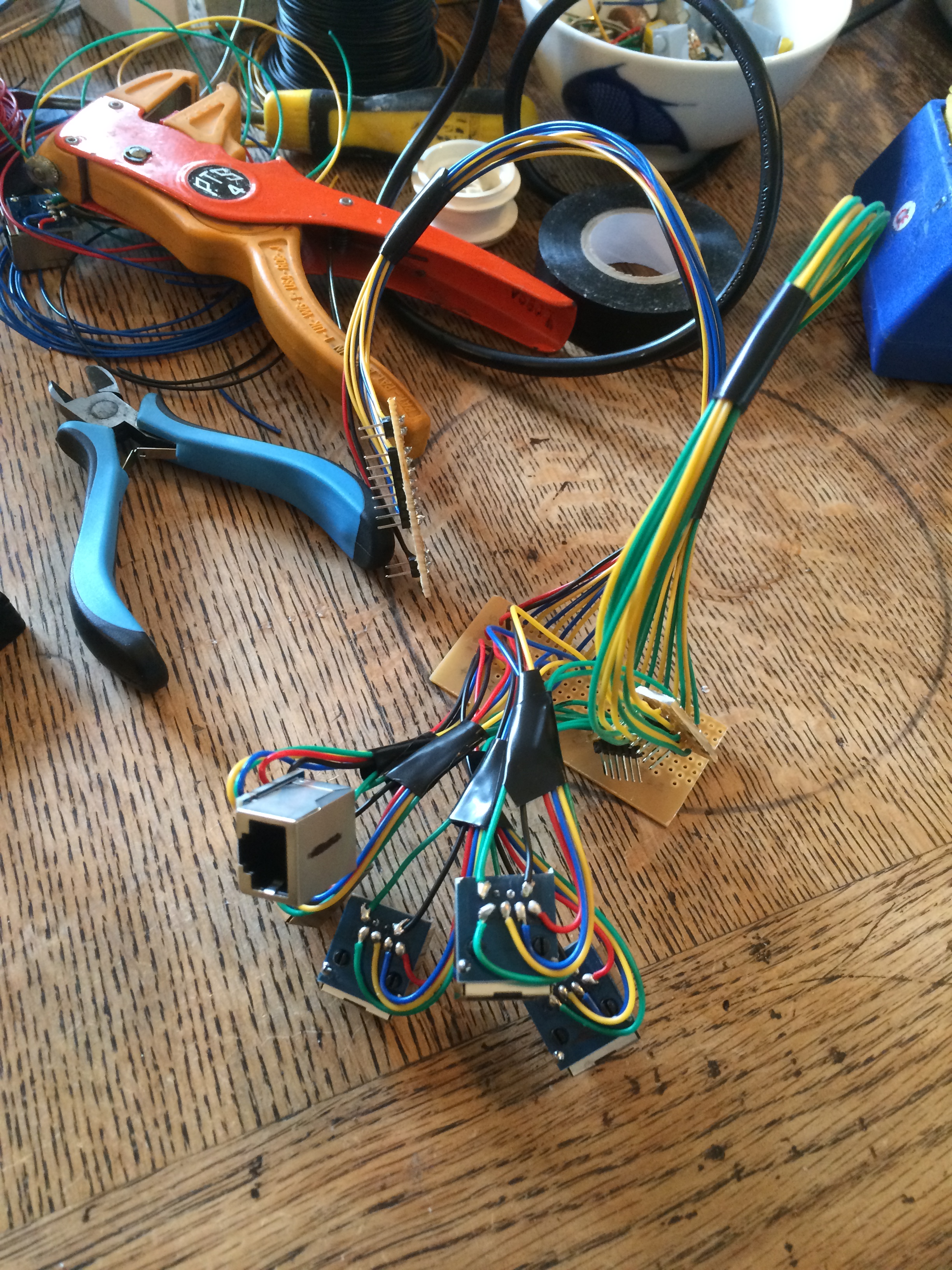
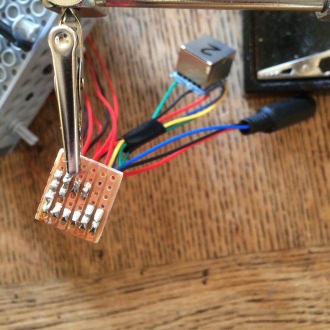
Brilliant, now we have an easy way of connection. Now the focus was back to the Lego units, and more importantly the balls. We wanted a way of being able to take the balls off the strings and also being able to disconnect them from the ethernet port on the Lego units themselves (see the last picture of this post to see how it all looks). We resolved this problem by using 3.5mm stereo plugs and sockets as they have three connectors and this was all we needed. We could also colour code the wire so it was easier to set up. Unfortunately though we ran out of green wire so the green LEDs actually use blue wire (a bit confusing but at least the ground was still black and the red LED used red wire).
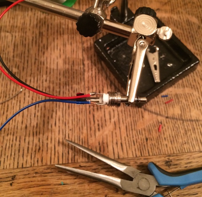
Here is a picture of soldering the plug.
And here all of the plugs and sockets together:
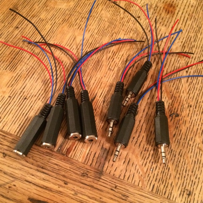
If you are eagle eyed you will notice that there is one missing. This is because we made a prototype cable before to check if it worked, but it used a yellow instead of blue wire so it didn’t fit as well into the picture (colours are important you know?).
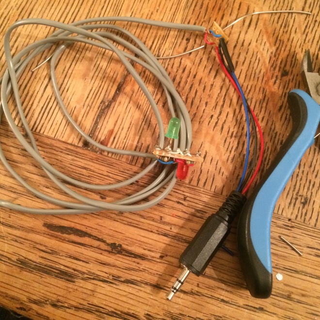
Here is it all assembled. Now, before getting into this picture we would like to clarify a few timeline issues. We actually made the cables at the same time as making the balls, but we wanted to keep all of the cabling issues inside one post to make it a bit nicer. You can tell that we did them at the same time as the balls because this picture if of the cable attached to one of the original light systems, rather than the new and improved version.
We also used a small piece of stripboard to attach the grey cable to the other component cables, because the grey cable was far to delicate to mount inside the plugs. In order for the solder to stick properly inside the plug, the metal of the plug itself had to be at a certain temperature. But this took some time as it is quite thick, and when the metal got to that temperature, it melted the cable which made it short with itself. Stripboard was much more efficient as it is very quick to get up to the right temperature.
Bringing Everything Together:
Now it was time to bring everything together at the string potentiometer end. This involved soldering the ethernet sockets to the potentiometers and also to the 3.5mm sockets. And this is what it looked like:
Very tidy. And now its ready to go…
