In the prototyping videos so far, the part which the user holds to interact with the system has been a series of cans. Obviously these won’t be in the final design. Instead we will be using clear plastic balls with LEDs inside them, which is where the ‘glow’ in toneglow comes from.
Wiring:
The major problem we have to face is how to wire the LEDs without interfering with the string system too much. The first thought we had was to use a system of pulleys with a wire so that when the ball is lifted the pulley goes down. Here is a diagram to further explain:
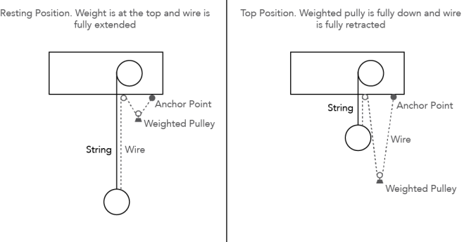
After trialling a mock up, we found that the pulley got in the way of the ball and was quite invasive on the space which people were using to move the ball up and down. It was also very difficult to find a three core wire (Ground, LED 1, LED 2) which would be flexible enough to work properly with a pulley.
We racked our brains for what seemed like an age, coming up with novel but ultimately ineffective ideas. Eventually we came up with the solution of just having the wire hanging freely and just be attached to the ball and the top of the string. This means that the wire doesn’t get in the way with any weights and can easily move where it needs to. We also think it makes the system look more natural and free as if there isn’t too much holding it.
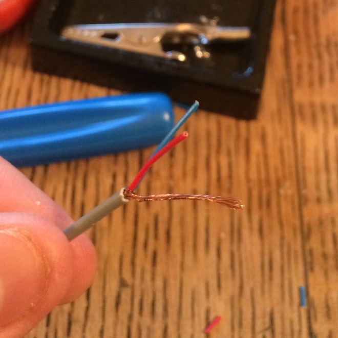
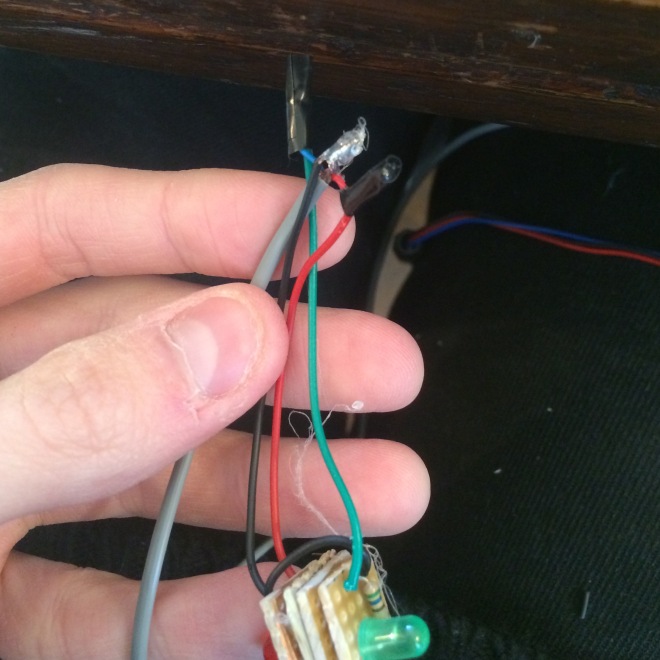
We found some wire at Maplin which seemed perfect for our needs. It is shielded audio cable which has two cores and a protective sheath of wire around them. We figured that we could collect and move the sheath to one side which would allow us to solder it to the board and use it as a ground. These images illustrate how the wire looked before and after:
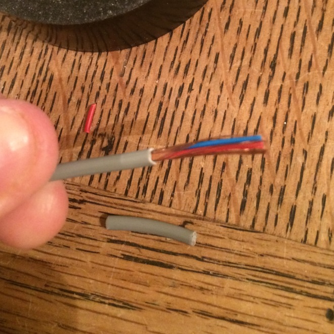
The sheath was very easily separated and twisted into its own section.
This wire is very thin and flexible which is perfect for our needs as it hangs quite loosely in quite a nice fashion.
This is how the wire looks when it is hanging:
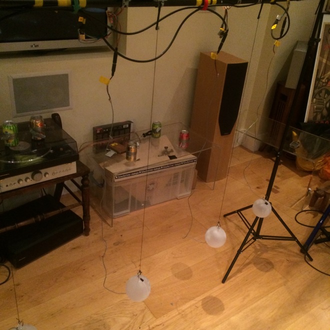
This is a picture of prototype 3 which is fully built. Its build will be covered in the next blog post, but you can see how the wire hangs.
The Balls:
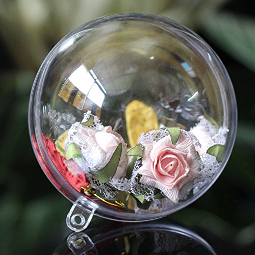
For the balls to use for the final installation, we ordered some transparent plastic Christmas baubles from amazon. They come in two halves so you can put whatever you want inside them. They look like this (minus the flowers and things):
Initially we thought it would look quite nice if you could see the lights inside on the circuitboard. We thought it would look more ‘science-ey’, but we quickly realised it wouldn’t give us the type of diffusion we were looking for in the lighting. To remedy this, we bought some frosting spray paint which made the balls look like this:
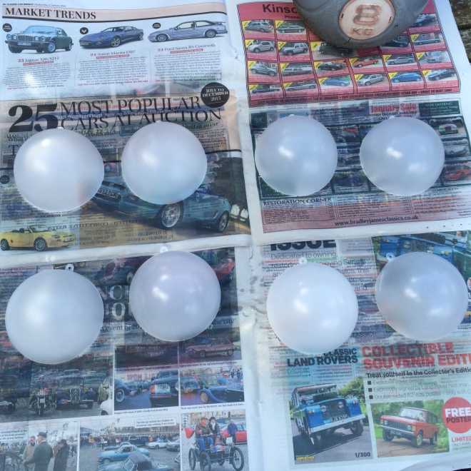
After painting we realised that it was indeed a very good idea. The frosting gave a really nice texture to the plastic and was very effective at diffusing the light in the end. But that will be covered when we get to it.
The Lights:
The lights were unexpectedly difficult to produce due to the terrible mistake of building something without properly testing it (we learned to do proper thorough testing after this incident!)
Essentially, we wanted two different coloured LEDs, of which one would react to the pulling up and down motion, and the other would react to the back and forth swinging motion. Each one would light up a different side of the ball so that the colours would be more obvious and linked to the movement of the ball.
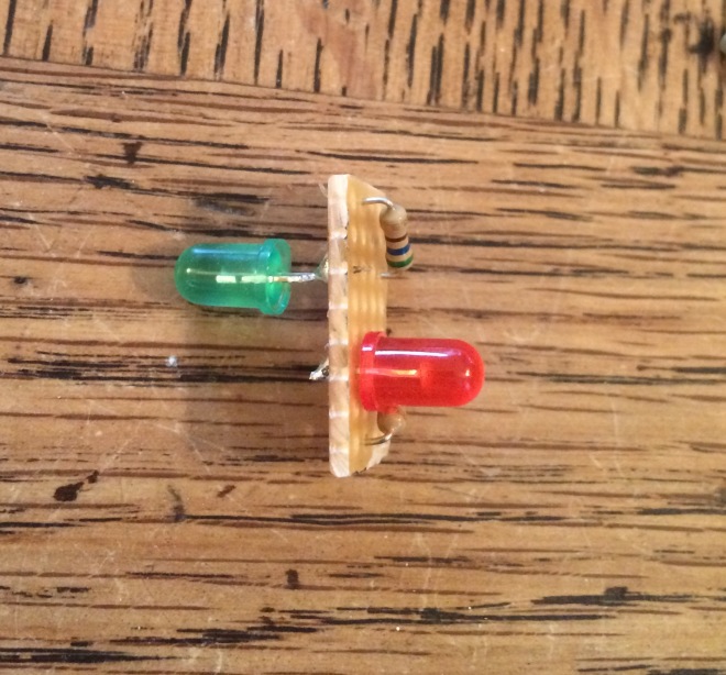
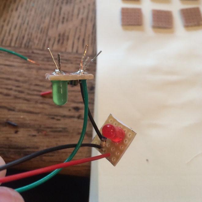
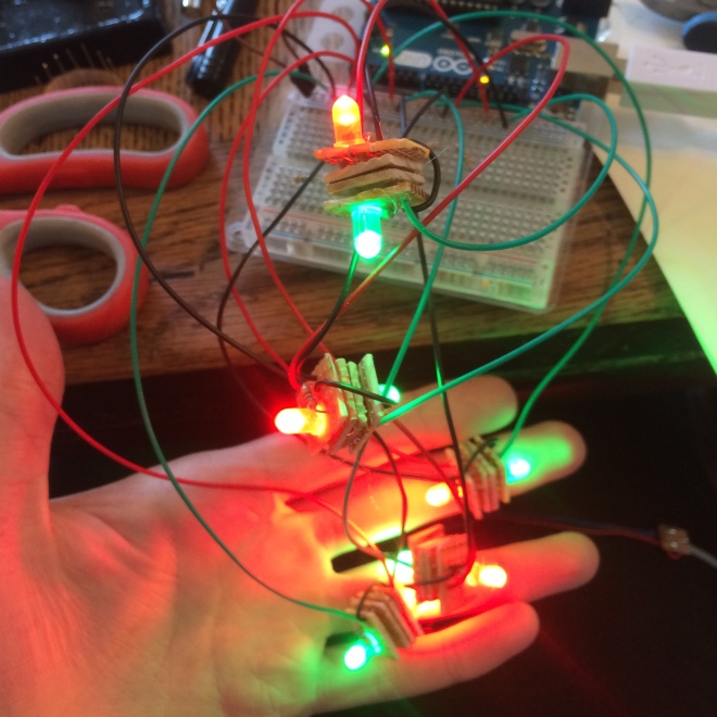
For the first iteration of the lights we decided to go for a very simple solution of soldering each light to its own breadboard and having a common ground between them. We forgot to take pictures during the building stage, but this image shows it quite simply:
The breadboards are taped back to back with some tape between them so they don’t short circuit. They are then glued with a small blob of hot glue to two toothpicks to be mounted into the inside of the ball, and a small notch was cut out of the ball with a dremel to allow the wire through. With some quick programming in Arduino this was the result of the first ball:
Here is the code for this ball, it includes the functions to control the LEDs. The values are smoothed because sometimes there are outliers in the sensor information and make the red LEDs flash in their resting position which they are not meant to do. The smoothing helps eliminate these values. We decided not to output the smoothed values to Max/MSP because it creates a bit of a delay in the sound when you move the balls around, and the outliers have a lot less of an effect on the sound. The up and down motion controls the brightness of the green LED and the back and forth motion controls the brightness of the red LED.
//This is the code for Prototype 2.5, the test for one ball with LEDs

const int one = A0;
const int two = A1;

int ledOne = 2;
int ledTwo = 3;

int brightness;
int bbrightness;
int brightnessOne;
int brightnessTwo;

//smoothing

/////////// smoothing A0 ///////////
const int numReadingsA0 = 10;
int readingsA0[numReadingsA0];
int readIndexA0 = 0;
int totalA0 = 0;
int averageA0 = 0;
//////////////////////////////////////

/////////// smoothing A1 ///////////
const int numReadingsA1 = 10;
int readingsA1[numReadingsA1];
int readIndexA1 = 0;
int totalA1 = 0;
int averageA1 = 0;
//////////////////////////////////////


void setup()
{
 Serial.begin(9600);

 // initialize all the readings to 0:
 /////////// smoothing A0 ///////////
 for (int thisReadingA0 = 0; thisReadingA0 < numReadingsA0; thisReadingA0++) {readingsA0[thisReadingA0] = 0;}

 /////////// smoothing A1 ///////////
 for (int thisReadingA1 = 0; thisReadingA1 < numReadingsA1; thisReadingA1++) {readingsA1[thisReadingA1] = 0;}


 pinMode(ledOne, OUTPUT);
 pinMode(ledTwo, OUTPUT);


}

void loop()
{

 /////////// smoothing A0 ///////////
 totalA0 = totalA0 - readingsA0[readIndexA0];
 readingsA0[readIndexA0] = analogRead(one);
 totalA0 = totalA0 + readingsA0[readIndexA0];
 readIndexA0 = readIndexA0 + 1;
 if (readIndexA0 >= numReadingsA0) {
 readIndexA0 = 0;
 }
 averageA0 = totalA0 / numReadingsA0;
 //////////////////////////////////////

 /////////// smoothing A1 ///////////
 totalA1 = totalA1 - readingsA1[readIndexA1];
 readingsA1[readIndexA1] = analogRead(two);
 totalA1 = totalA1 + readingsA1[readIndexA1];
 readIndexA1 = readIndexA1 + 1;
 if (readIndexA1 >= numReadingsA1) {
 readIndexA1 = 0;
 }
 averageA1 = totalA1 / numReadingsA1;
 //////////////////////////////////////


 brightness = averageA0;
 bbrightness = averageA1;

 // using the map function as a sort of calibration.
 // you have to input the minimum and maximum values of where you want the ball to be
 // and input it into the map function to give the desired outputs

 // brightness one is the red led and is controlled by swing, if it is pulled
 // towards you then it gets brighter

 // brightness two is controlled by the up/down motion. if the ball is raised the
 // green LED becomes dimmer
 brightnessOne = map(brightness, 470, 660, 0, 255);
 brightnessTwo = map(bbrightness, 285, 685, -255, 255);

//limit the brightness so it doesn't wrap if the map function goes over its limits
 if (brightnessOne > 244) {brightnessOne = 255;}
 if (brightnessOne < 1 ) {brightnessOne = 0 ;}
 if (brightnessTwo > 244) {brightnessTwo = 255;}
 if (brightnessTwo < 1 ) {brightnessTwo = 0 ;}

 analogWrite(ledOne, brightnessOne);
 analogWrite(ledTwo, brightnessTwo);


 Serial.print(analogRead(one));
 Serial.print(",");
 Serial.println(analogRead(two));

}
Here is a very quick video explaining the Maxpatch behind it.
It works! Now it’s tome to build some more.
And this is where the fatal mistake happened…
We decided to do the drastic deed of redesigning the circuit without making a prototype and making all five at once.
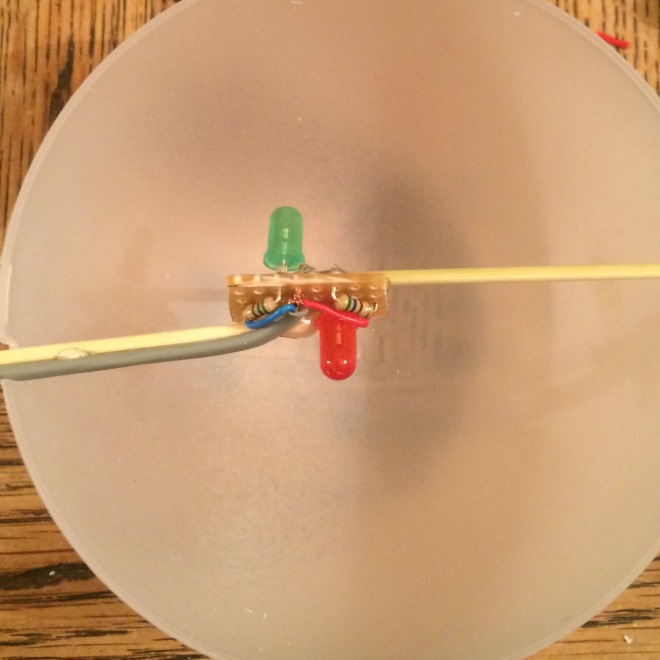
We decided to mount the two lights to one board and have a common ground on one board and the two control wires going to each side. This is it looked like:
The stripboard was cut in the right places at the back so the circuit didn’t short (or so we thought) and after mounting this is what it looked like:
As mentioned earlier, we made and tested 5 of these without testing properly. We tested whether each light came on but we didn’t test whether they would both come on at the same time.
After all that time building and gluing we became quite angry so did not take a video of it not working properly, but the problem was that only the red light was illuminating, even when both were connected to power, which was down to bad circuit design. We checked the stripboards over and over again for shorts and bad design elements but we could not for the life of us figure out what was going wrong. Time was becoming short before we had to present it to the public so we decided to go back to the slightly uglier prototype method, but we figured that because the lights would be inside the balls, then no one would see the ugliness which lay below.
The Lights Mark 2 (But really back to the prototype):
So, after running out of time (and components) we decided to recycle and rebuild. Like mentioned before, we went back to the original design but tweaked it slightly to make it more rugged.
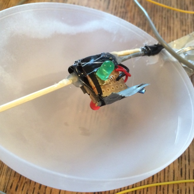
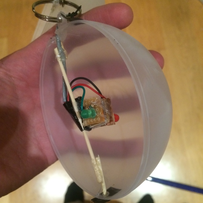
Here is an exploded view of what the final lights look like:
This is before the wires were cut but we tested and tested to make sure these worked and they did!
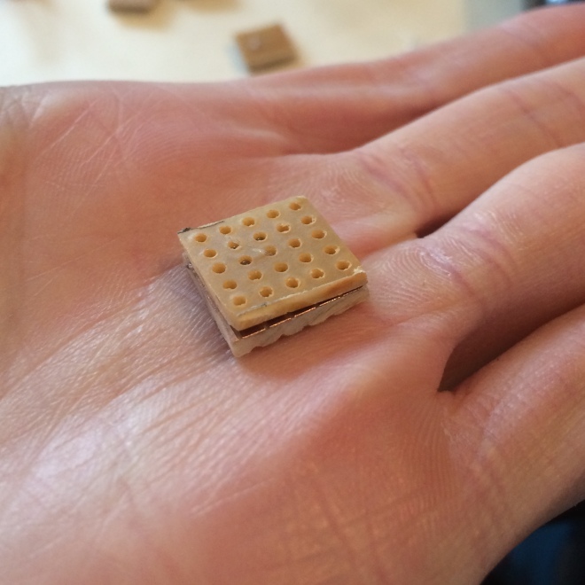
Instead of putting tape between the two breadboards, we decided to put more breadboards. We didnt want to risk one of the sharp solder joints poking through to the other board and short circuiting it so we created these little back to back glued stripboard parts to put in between:
There’s no risk of shorting here any more.
Heres what they looked like when glued between the LED boards:
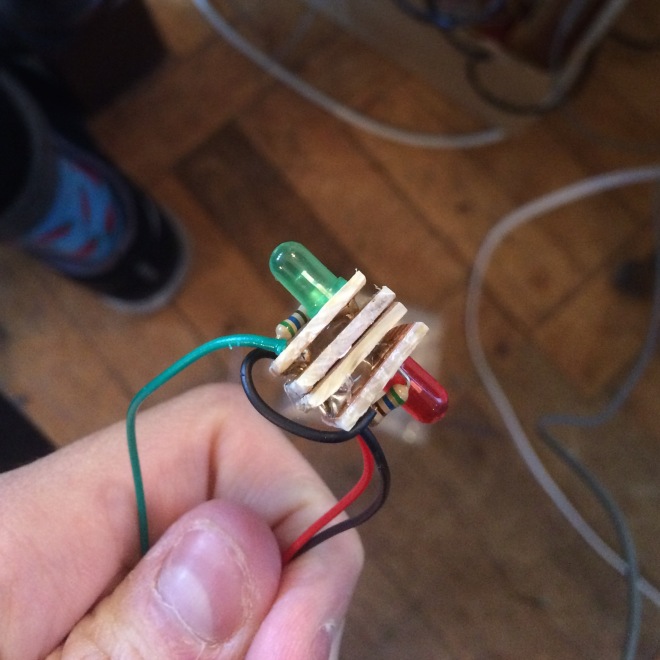
They are a fair bit larger than the other version, but they are solid and they work properly as seen in this picture:
I don’t think anyone has been as emotional as we were seeing them all work in harmony. But now it was time to mount them inside the balls.
As a side note, you may have noticed that we didn’t solder the grey wire directly to the stripboard. This was because its quite delicate and has an unguarded ground, so we didn’t want to stretch it out too much over the two stripboards in fear of shorts and wires being cut. So instead we soldered the grey wire to the patch wires poking out and covered the ends in hot glue and tape:
We then folded the wire over and glued it to the side of the board and to the toothpicks inside the balls. We decided to cut the existing toothpicks in half and just mount them to those to not risk breaking the balls. The inside final product looked like this:
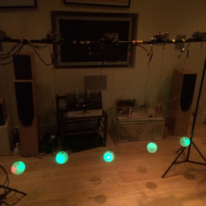
They work! You will have to wait until the final video to see them all working in harmony, but this picture shows them all being illuminated:
Now for the next issue. The Wiring.
