After building the first string potentiometer system, we went on to build 4 more to increase the user interaction and to be able to get more people to be able to use the system.
The first problem we had to tackle was that when there is no protective face on the side of the spring of the keyrings, the spring has a tendency to eject itself from the housing once pulled, like this:


We decided to glue a small plastic cover over the top in order to keep it inside and then glue the lego wheel over the top, this caused its own problems which will be elaborated upon later:
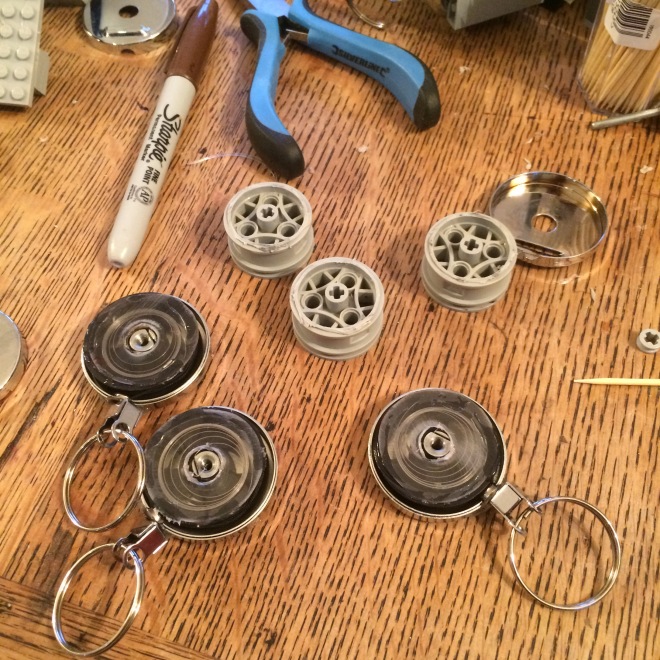
The building process for the new controllers is very similar to that of the first, so some steps have been skipped in order to make this post a bit more concise. Here are some pictures of the multiple pieces being constructed


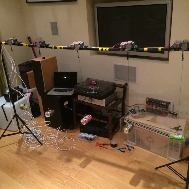
Here is a picture of all of the new controllers mounted to the bar.
This is a video of it in action!
One of the major problems we encountered with this was that the keyrings are not very smooth in their rotation, and it was incredibly hard to align the lego wheel with the centre of rotation, as the spindle with the string on it did not really stay centred through its rotation. Becuase of this, it moves around quite a lot, which ends up moving the Lego pieces and eventually making them come loose and falling off the top. Most of the pieces are glued together to prevent this, but we wanted to keep the keyring side of it modular so we don’t have to change the whole gearbox if we want to change the system. The system works fine for a prototype, but we need to make it more tough if it is going to withstand the constant use from people moving it around, it needs to be virtually bombproof so that people who don’t necessarily know how delicate it is can use it without us having the fear of it breaking.
Glueing the Plastic cover and Lego wheel to the internal unit worked, but the main and most irritating problem was that if this part came away from the metal housing (which was incredibly easy for it to do) the spring would unravel and be incredibly hard to reattach to the spindle. This is the main feature which needs to be improved, the ability to fix it easily if it breaks.
We are going to start thinking about a way to create a more stable implementation for this system, keeping it more centred.
Building multiple controllers came with a new set of problems which boiled down to two major parts: keeping consistency and routing and keeping a handle on wires. Originally, the first prototype used 4 individual wires taped together going straight into a breadboard, which worked fine, but was a bit fiddly. Multiplying these wires by a factor of 5 exponentially increased the confusion of wires going into the breadboard and reliability of connection due to some wires unexpectedly pushing on each other and coming loose. We decided that instead of using individual wires that we would use ethernet cable. Ethernet cable has 8 cores, so plenty for each unit, even if we wanted to expand functionality (for example, adding LEDs ) then we could just use more of the wires inside the cable. The flaw of ethernet cable though is that it is quite stiff, so it is hard to plug into a breadboard for testing. Eventually we will make a stripboard unit which can take all of the inputs and spread them out properly, and be properly housed with connectors for easily plugin into the Arduino. At the minute the cables are hardwired to each module so if we did this it would mean that they will all be connected together and just create a massive tangle of cables. We thereore need to make some plugs which we can remove easily from each module, and also to the Arduino. We will probably use ethernet plugs (as it is ethernet cable) so they can easily be clipped together and apart.
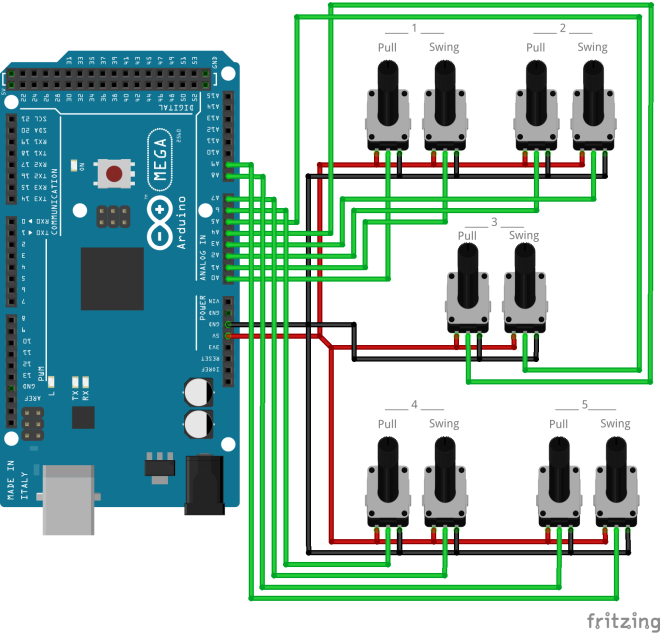
Fritzing Diagram:
Code:
This code is fairly simple as it just reads values and outputs them to Max/MSP.
//This is the code for Prototype 2 with five cans

const int one = A0;
const int two = A1;
const int three = A2;
const int four = A3;
const int five = A4;
const int six = A5;
const int seven = A6;
const int eight = A7;
const int nine = A8;
const int ten = A9;


void setup()
{
 Serial.begin(9600);
}

void loop()
{
 // output analog values as serial data to be read by Max
 Serial.print(analogRead(one));
 Serial.print(",");
 Serial.print(analogRead(two));
 Serial.print(",");
 Serial.print(analogRead(three));
 Serial.print(",");
 Serial.print(analogRead(four));
 Serial.print(",");
 Serial.print(analogRead(five));
 Serial.print(",");
 Serial.print(analogRead(six));
 Serial.print(",");
 Serial.print(analogRead(seven));
 Serial.print(",");
 Serial.print(analogRead(eight));
 Serial.print(",");
 Serial.print(analogRead(nine));
 Serial.print(",");
 Serial.println(analogRead(ten));
}
Max Video:
Here is a video describing the maxpatch for this protytpe. In this video I also describe the problem of ambiguity in sound, especially when there are 5 controllers in use, and also the way it has been overcome.
