Building a String Potentiometer With Lego
It’s time to start building something
For the string potentiometer we wanted to use a Lego gearbox to map the many turns of a retractable keyring to a small enough amount to turn the potentiometer.
So we made this:
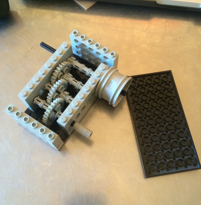
It is a very simple sequence of gears which all have a ratio of 1:3, therefore the final ratio is 1:9, so one full turn of one side will turn the other side 9 times. This therefore means that I will need 6.75 turns of the lower geared side to turn a potentiometer through its whole 270 degree sweep.
Skip forwards a bit (because we forgot to take pictures) to this:
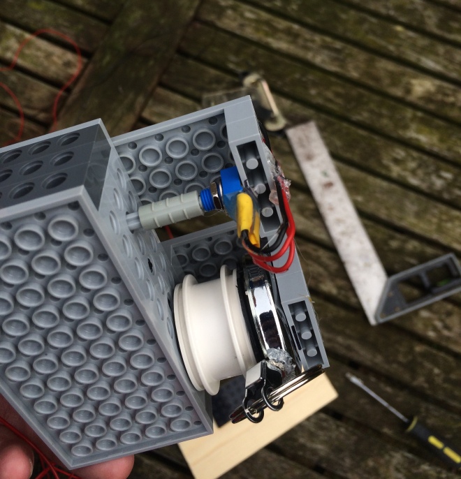
This is a lego wheel glued to a retractable keyring on one side so that it turns the wheel, and a potentiometer glued via a lego gearbox to a potentiometer on the other side. The whole range of the keyring only turns the potentiometer about a quarter of a turn. In the final versions, there will probably be a longer range for the string to travel so the potentiometer will turn more. The wire connections are covered in hot glue to prevent shorts and create some stress relief.
This is the part which the string goes through, it measures the tilt of the string via a potentiometer and can send the information to the Arduino.
If you’re reading this after our introduction, you will have noticed that we mentioned the use of distance sensors for the back/forth motion. The reason we didn’t go with these in the end was because there is no guarantee that they would always be facing the wall as they might spin around, and we also didn’t want to limit our project to only being installed next to a wall. The surface of the wall would also have a marked effect on the reaction of the sensor, for example, if it was glossy it wouldn’t give accurate feedback. Due to these shortcomings of distance sensors, we decided that this physical string tilt system would be the best for our needs.
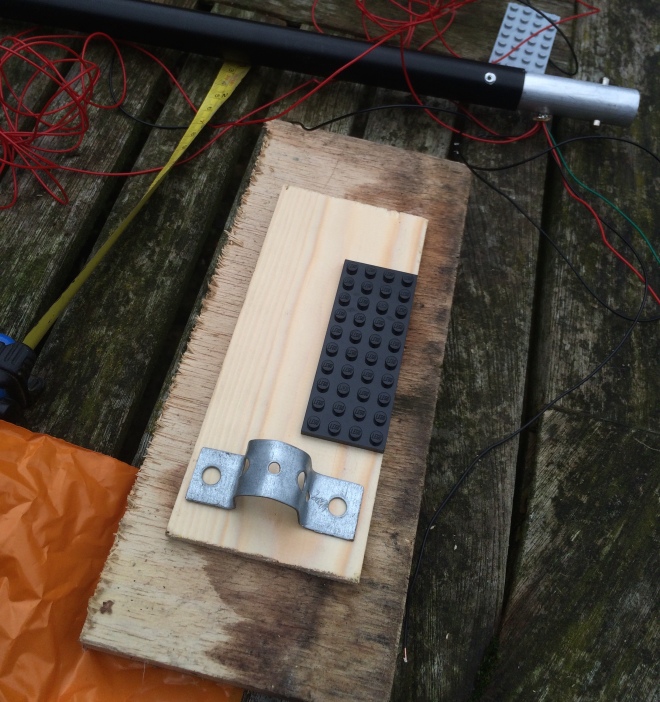
It will be mounted to a green screen stand like this:

https://d29h7ql7qnxkqx.cloudfront.net/pix/discountbulbs/support_bwg-4.jpg
It is essentially a bar mounted to two tripods, so we needed to figure a way to mount the lego to it. We glued a Lego plate to a piece of wood which has metal mounting points.
This is the first metal mount which is moulded to the pipe size.
Here is a picture of bending the metal in a vice
We drilled a few holes to mount a nut and bolt to the metal parts, these can easily be tightened to clamp on to the bar. I am going to put wing nuts on it to make it easier to tighten and remove.
Here it is mounted to the bar, you can see the string is routed through the lego axle. The wire is hot glued to the lego to keep it secure and provide strain relief.
Heres a closer up picture of the routing. The metal part is there so the string doesn’t fly back up into the retractable keyring. This happened once and it took a long time to fish it back out.
One of the problems faced with the mark One version is that I wanted to make it easy to dismantle and reattach so it is more portable. But the string potentiometer section is fairly fragile and can easily come apart, the spring can come unattached if you pull the side part off. Also it moves around quite a lot as it was hard to mount the wheel perfectly centrally on the keyring, and also the tension of the spring always pushes the wheel to one side so it pushes out as it is rotated, as in this diagram.
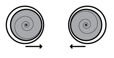
The spring pushes from central point outwards. Because the internal wheel of the keyring which holds the spring and string is connected to a wheel which had a hole in the middle which was slightly bigger than the spindle it was attached to, it didn’t remain centred and was always pushed out from the centre in some direction
Here is a video of it in action
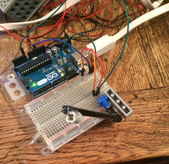
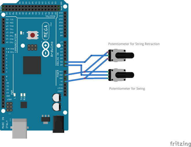
Fritzing Diagram:
The actual circuit for the first prototype is incredibly simple once its shrunk down. Essentially the final version of this just has extended wires going to the gearboxes.
Code:
This is the code for the first prototype, it is incredibly simple as it just needs to take the potentiometer values and spit them out through the serial port into Max.
//This is the code for Prototype 1 with one can

const int one = A0;
const int two = A1;

void setup()
{
 Serial.begin(9600);
}

void loop()
{
 Serial.print(analogRead(one));
 Serial.print(",");
 Serial.println(analogRead(two));

}
Max Video:
Here is a quick video overviewing how the Maxpatch works:
