We initially intended toneglow to be an interactive installation which could bring people together through the means of making music with a physical system. We wanted to make a system which made it easy to create music no matter what ones musical or technological background or experience was, and one which had a close relationship between the movement, lighting produced and sound created.
Technically we had strong ideas from the beginning about toneglow’s construction and implementation and due to this they were not changed too much from their initial conception. We changed:
Distance sensors on the back became a lever at the top of the string. This was because we felt that distance sensors were unreliable in outputted data, and their orientation would be hard to fix as the balls could spin around and make them face away from the wall. We also did not want to be constrained to just having the project installed next to a wall as we wanted open spaces to be an option for installation.
We reduced the number of controllers created from our estimated six to eight, down to five. This was partially due to time constraints, and also because we thought the system could become cluttered, and the sound produced could become too ambiguous.
We did not end up using RGB LEDs primarily because we wanted each side of the ball to light up a certain colour. Also just having two colours reduced the amount of wiring required from each ball from if we had had 3 colours. A system using RGB LEDs could be interesting in future iterations though, as it could let us make any colours we wanted, so the system could be fit into any environment.
Because of our strong ideas from the outset, we faced less issues based around aesthetic design, and more based around technical challenges. For example, the most time consuming challenge we faced was when we wired the LEDs the wrong way and had to think of a way to do it properly which involved returning to the prototype phases. The thought behind building a string potentiometer was also very time consuming, and Lego was a complete and utter moment of divine inspiration which ended up being incredibly successful despite some initial doubts.
Future possibilities?
Much like many projects of the same ilk as toneglow, the possibilities are nearly limitless with how we can expand in physical and musical ideas. Some of the more pressing ideas we thought could be improved are:
Stronger and more visually appealing housing. As the project progressed, we became more fond of the stripped back aesthetic of the system, but in the installation context in which we want toneglow to shine, ruggedness is quite crucial, and having delicate wires hanging everywhere is not really ideal. The Lego housing, although it did not break catastrophically at any point, definitely has the possibility to do so, especially if someone who hasn’t been versed on the more careful use of toneglow were to be aggressive with it. Even though the Lego works perfectly fine, a more enclosed and bespoke enclosure would definitely work more efficiently and reliably.
Ambiguity in sound was another main issue. Making the effect which each person has on the audio produced more explicit is an issue which has been faced since day one. Although we feel we helped this issue with harmonic phasing and FM modulation of sine waves to make certain sounds more distinct, there is surely some way to go in the implementation of sound.
Expanding the project to a larger scale would be incredibly interesting, because at the minute it is installed in what is essentially a 2-dimensional plane, which limits the depth of interaction. Having different units dotted around a room would open up more possibilities for user interaction as they have more options for their bodily orientations.
Interactions between controllers could also be improved. At the minute, toneglow is quite segmented in the sense that each controller has its own definite function, and that is what it does. Having one controller affecting how another one behaves, or having certain behaviours triggered if many are used at once would add a whole new dimension to the interactions and sounds possible to produce.
Having different behaviours from variations in use of the toneglow would also be interesting. For example, using acceleration and speed of movement as a control for certain lighting or sound cues could add more interest to the use of the system.
Code-wise, a small improvement would be to change the smoothing algorithm used for the analogue inputs, at the minute some outliers have unexpected effects on the lights which can happen quite randomly.
Installation in a wider variety of spaces is definitely something which we want to look into. For example, galleries as an exhibit, or schools as an educational or therapeutic system.
In Conclusion
We feel that we surpassed what we set out to achieve, and through the final testing and information from the interviews, the reaction which toneglow elicited was beyond our expectations. We are incredibly happy with what we have produced, and definitely believe that future expansions and possibilities for design are very close on the horizon.
We asked a few questions at the end to gauge people’s responses to it. we seemed to receive a very positive response from people, and they really seemed to enjoy using the system. We will cover this more in our final evaluation.
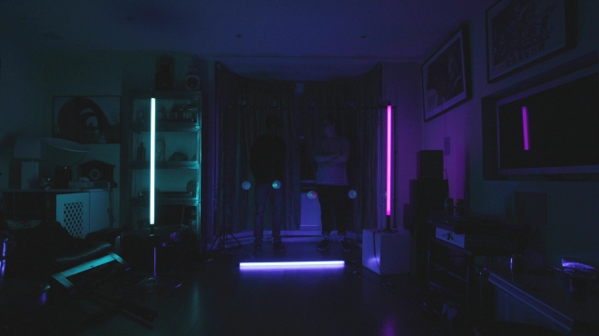
In the video you can hear the effects of not outputting the smoothed data to Max/MSP, especially in the establishing shots (where you can actually see one of the sliders moving a bit randomly). As mentioned in the previous blog post, we felt that this added some depth to the sound and made it more interesting, especially in its resting state.
This is it. This is the culmination of all of our work so far, in the final prototype, which will end up becoming the final product. So far there have only been iPhone quality pictures but now behold, toneglow.
The system has not gone through any major changes since its first iteration, and I think this is largely because we had a strong idea of what we wanted to create from the beginning. The major differences are that we didn’t use distance sensors due to the issues discussed in the first prototype blog post, and we only ended up making 5 control units. This was partially due to time constraints and the ambiguity in the sound which each one controlled. Ultimately though, with the bar we had and the scale we were creating, 6 balls or more would have been too cluttered and probably would have tangled with each other or something like that. There have been some setbacks along the way, but this was to be expected. And ultimately we are very happy with the result we were left with.
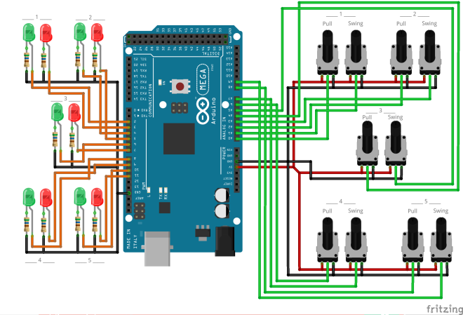
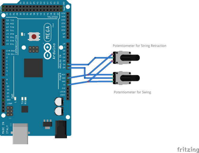
Fritzing Diagram:
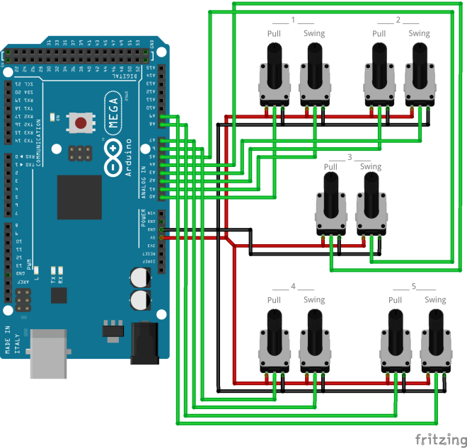
This is essentially a condensed version of how the system works. In the actual one all the cables are extended and routed with ethernet cables, but i thought this would take too much unnecessary space.
Code:
You will notice that the code for this prototype has gone through some substantial changes. Most noteably, the smoothing. This is because we found that as we added more inputs, the analogue values became more and more rough, throwing outliers all over the place. The smoothing helps with this, it means the LEDs don’t flash all over the place and do things they aren’t meant to do. You may notice that we have deliberately not outputted the smoothed data to Max/MSP, this is because we quite liked the random blips of data being sonified, and they give more sonic dynamics, especially when the system is in its resting state.
//This is the code for Prototype 3 with 5 balls with LEDs
//It is also the final code

const int one = A0;
const int two = A1;
const int three = A2;
const int four = A3;
const int five = A4;
const int six = A5;
const int seven = A6;
const int eight = A7;
const int nine = A8;
const int ten = A9;

int ledOne = 2;
int ledTwo = 3;

int ledThree= 4;
int ledFour = 5;

int ledFive = 6;
int ledSix = 7;

int ledSeven = 8;
int ledEight = 9;

int ledNine = 10;
int ledTen = 11;

int brightness;
int bbrightness;

// brightness for rel LEDs
int brightnessOne;
int brightnessTwo;
int brightnessThree;
int brightnessFour;
int brightnessFive;

//For the pulsating green light
int pulseBrightness;
float pulseRate;

//smoothing modified from https://www.arduino.cc/en/Tutorial/Smoothing

/////////// smoothing A0 ///////////
const int numReadingsA0 = 10;
int readingsA0[numReadingsA0];
int readIndexA0 = 0;
int totalA0 = 0;
int averageA0 = 0;
//////////////////////////////////////

/////////// smoothing A1 ///////////
const int numReadingsA1 = 10;
int readingsA1[numReadingsA1];
int readIndexA1 = 0;
int totalA1 = 0;
int averageA1 = 0;
//////////////////////////////////////

/////////// smoothing A2 ///////////
const int numReadingsA2 = 10;
int readingsA2[numReadingsA2];
int readIndexA2 = 0;
int totalA2 = 0;
int averageA2 = 0;
//////////////////////////////////////

/////////// smoothing A3 ///////////
const int numReadingsA3 = 10;
int readingsA3[numReadingsA3];
int readIndexA3 = 0;
int totalA3 = 0;
int averageA3 = 0;
//////////////////////////////////////

/////////// smoothing A4 ///////////
const int numReadingsA4 = 10;
int readingsA4[numReadingsA4];
int readIndexA4 = 0;
int totalA4 = 0;
int averageA4 = 0;
//////////////////////////////////////

/////////// smoothing A5 ///////////
const int numReadingsA5 = 10;
int readingsA5[numReadingsA5];
int readIndexA5 = 0;
int totalA5 = 0;
int averageA5 = 0;
//////////////////////////////////////

/////////// smoothing A6 ///////////
const int numReadingsA6 = 10;
int readingsA6[numReadingsA6];
int readIndexA6 = 0;
int totalA6 = 0;
int averageA6 = 0;
//////////////////////////////////////

/////////// smoothing A7 ///////////
const int numReadingsA7 = 10;
int readingsA7[numReadingsA7];
int readIndexA7 = 0;
int totalA7 = 0;
int averageA7 = 0;
//////////////////////////////////////

/////////// smoothing A8 ///////////
const int numReadingsA8 = 10;
int readingsA8[numReadingsA8];
int readIndexA8 = 0;
int totalA8 = 0;
int averageA8 = 0;
//////////////////////////////////////

/////////// smoothing A9 ///////////
const int numReadingsA9 = 10;
int readingsA9[numReadingsA9];
int readIndexA9 = 0;
int totalA9 = 0;
int averageA9 = 0;
//////////////////////////////////////


void setup()
{
 Serial.begin(9600);

 // initialize all the readings to 0:
 /////////// smoothing A0 ///////////
 for (int thisReadingA0 = 0; thisReadingA0 < numReadingsA0; thisReadingA0++) {readingsA0[thisReadingA0] = 0;}

 /////////// smoothing A1 ///////////
 for (int thisReadingA1 = 0; thisReadingA1 < numReadingsA1; thisReadingA1++) {readingsA1[thisReadingA1] = 0;}

 /////////// smoothing A2 ///////////
 for (int thisReadingA2 = 0; thisReadingA2 < numReadingsA2; thisReadingA2++) {readingsA2[thisReadingA2] = 0;}

 /////////// smoothing A3 ///////////
 for (int thisReadingA3 = 0; thisReadingA3 < numReadingsA3; thisReadingA3++) {readingsA3[thisReadingA3] = 0;}

 /////////// smoothing A4 ///////////
 for (int thisReadingA4 = 0; thisReadingA4 < numReadingsA4; thisReadingA4++) {readingsA4[thisReadingA4] = 0;}

 /////////// smoothing A5 ///////////
 for (int thisReadingA5 = 0; thisReadingA5 < numReadingsA5; thisReadingA5++) {readingsA5[thisReadingA5] = 0;}

 /////////// smoothing A6 ///////////
 for (int thisReadingA6 = 0; thisReadingA6 < numReadingsA6; thisReadingA6++) {readingsA6[thisReadingA6] = 0;}

 /////////// smoothing A7 ///////////
 for (int thisReadingA7 = 0; thisReadingA7 < numReadingsA7; thisReadingA7++) {readingsA7[thisReadingA7] = 0;}

 /////////// smoothing A8 ///////////
 for (int thisReadingA8 = 0; thisReadingA8 < numReadingsA8; thisReadingA8++) {readingsA8[thisReadingA8] = 0;}

 /////////// smoothing A9 ///////////
 for (int thisReadingA9 = 0; thisReadingA9 < numReadingsA9; thisReadingA9++) {readingsA9[thisReadingA9] = 0;}


 pinMode(ledOne, OUTPUT);
 pinMode(ledTwo, OUTPUT);
 pinMode(ledThree, OUTPUT);
 pinMode(ledFour, OUTPUT);
 pinMode(ledFive, OUTPUT);
 pinMode(ledSix, OUTPUT);
 pinMode(ledSeven, OUTPUT);
 pinMode(ledEight, OUTPUT);
 pinMode(ledNine, OUTPUT);
 pinMode(ledTen, OUTPUT);

}

void loop()
{


 //for the pulsing of the Green LEDs
 pulseRate += 0.1;
 pulseBrightness = 45+(210*(((cos(pulseRate))+1)/2));

 /////////// smoothing A0 ///////////
 totalA0 = totalA0 - readingsA0[readIndexA0];
 readingsA0[readIndexA0] = analogRead(one);
 totalA0 = totalA0 + readingsA0[readIndexA0];
 readIndexA0 = readIndexA0 + 1;
 if (readIndexA0 >= numReadingsA0) {
 readIndexA0 = 0;
 }
 averageA0 = totalA0 / numReadingsA0;
 //////////////////////////////////////

 /////////// smoothing A1 ///////////
 totalA1 = totalA1 - readingsA1[readIndexA1];
 readingsA1[readIndexA1] = analogRead(two);
 totalA1 = totalA1 + readingsA1[readIndexA1];
 readIndexA1 = readIndexA1 + 1;
 if (readIndexA1 >= numReadingsA1) {
 readIndexA1 = 0;
 }
 averageA1 = totalA1 / numReadingsA1;
 //////////////////////////////////////

 /////////// smoothing A2 ///////////
 totalA2 = totalA2 - readingsA2[readIndexA2];
 readingsA2[readIndexA2] = analogRead(three);
 totalA2 = totalA2 + readingsA2[readIndexA2];
 readIndexA2 = readIndexA2 + 1;
 if (readIndexA2 >= numReadingsA2) {
 readIndexA2 = 0;
 }
 averageA2 = totalA2 / numReadingsA2;
 //////////////////////////////////////

 /////////// smoothing A3 ///////////
 totalA3 = totalA3 - readingsA3[readIndexA3];
 readingsA3[readIndexA3] = analogRead(four);
 totalA3 = totalA3 + readingsA3[readIndexA3];
 readIndexA3 = readIndexA3 + 1;
 if (readIndexA3 >= numReadingsA3) {
 readIndexA3 = 0;
 }
 averageA3 = totalA3 / numReadingsA3;
 //////////////////////////////////////

 /////////// smoothing A4 ///////////
 totalA4 = totalA4 - readingsA4[readIndexA4];
 readingsA4[readIndexA4] = analogRead(five);
 totalA4 = totalA4 + readingsA4[readIndexA4];
 readIndexA4 = readIndexA4 + 1;
 if (readIndexA4 >= numReadingsA4) {
 readIndexA4 = 0;
 }
 averageA4 = totalA4 / numReadingsA4;
 //////////////////////////////////////

 /////////// smoothing A5 ///////////
 totalA5 = totalA5 - readingsA5[readIndexA5];
 readingsA5[readIndexA5] = analogRead(six);
 totalA5 = totalA5 + readingsA5[readIndexA5];
 readIndexA5 = readIndexA5 + 1;
 if (readIndexA5 >= numReadingsA5) {
 readIndexA5 = 0;
 }
 averageA5 = totalA5 / numReadingsA5;
 //////////////////////////////////////

 /////////// smoothing A6 ///////////
 totalA6 = totalA6 - readingsA6[readIndexA6];
 readingsA6[readIndexA6] = analogRead(seven);
 totalA6 = totalA6 + readingsA6[readIndexA6];
 readIndexA6 = readIndexA6 + 1;
 if (readIndexA6 >= numReadingsA6) {
 readIndexA6 = 0;
 }
 averageA6 = totalA6 / numReadingsA6;
 //////////////////////////////////////

 /////////// smoothing A7 ///////////
 totalA7 = totalA7 - readingsA7[readIndexA7];
 readingsA7[readIndexA7] = analogRead(eight);
 totalA7 = totalA7 + readingsA7[readIndexA7];
 readIndexA7 = readIndexA7 + 1;
 if (readIndexA7 >= numReadingsA7) {
 readIndexA7 = 0;
 }
 averageA7 = totalA7 / numReadingsA7;
 //////////////////////////////////////

 /////////// smoothing A8 ///////////
 totalA8 = totalA8 - readingsA8[readIndexA8];
 readingsA8[readIndexA8] = analogRead(nine);
 totalA8 = totalA8 + readingsA8[readIndexA8];
 readIndexA8 = readIndexA8 + 1;
 if (readIndexA8 >= numReadingsA8) {
 readIndexA8 = 0;
 }
 averageA8 = totalA8 / numReadingsA8;
 //////////////////////////////////////

 /////////// smoothing A9 ///////////
 totalA9 = totalA9 - readingsA9[readIndexA9];
 readingsA9[readIndexA9] = analogRead(ten);
 totalA9 = totalA9 + readingsA9[readIndexA9];
 readIndexA9 = readIndexA9 + 1;
 if (readIndexA9 >= numReadingsA9) {
 readIndexA9 = 0;
 }
 averageA9 = totalA9 / numReadingsA9;
 //////////////////////////////////////


 brightness = averageA0;
 bbrightness = averageA1;

 // mapping brighntnesses for red leds
 brightnessOne = map (averageA1, 480, 630, 0, 255);
 brightnessTwo = map (averageA3, 500, 800, 0, 255);
 brightnessThree = map (averageA5, 450, 800, 0, 255);
 brightnessFour = map (averageA7,550, 800, 0, 255);
 brightnessFive = map (averageA9, 550, 800, 0, 255);


 // limiting values so they don't wrap if they go beyond the map function
 if (brightnessOne > 244) {brightnessOne = 255;}
 if (brightnessOne < 1 ) {brightnessOne = 0 ;}
 if (brightnessTwo > 244) {brightnessTwo = 255;}
 if (brightnessTwo < 1 ) {brightnessTwo = 0 ;}
 if (brightnessThree > 244) {brightnessThree = 255;}
 if (brightnessThree < 1 ) {brightnessThree = 0 ;}
 if (brightnessFour > 244) {brightnessFour = 255;}
 if (brightnessFour < 1 ) {brightnessFour = 0 ;}
 if (brightnessFive > 244) {brightnessFive = 255;}
 if (brightnessFive < 1 ) {brightnessFive = 0 ;}


 // red
 analogWrite(ledOne, brightnessOne );
 // green
 analogWrite(ledTwo, pulseBrightness);

 // red
 analogWrite(ledThree, brightnessTwo);
 // green
 analogWrite(ledFour, pulseBrightness);

 // the wiring on this one is slightly different so the lights are reversed
 //green
 analogWrite(ledFive, pulseBrightness);
 // red
 analogWrite(ledSix, brightnessThree);

 // red
 analogWrite(ledSeven, brightnessFour);
 // green
 analogWrite(ledEight, pulseBrightness);

 // red
 analogWrite(ledNine, brightnessFive);
 // green
 analogWrite(ledTen, pulseBrightness);


 //////// output to max ////////
 Serial.print(analogRead(one));
 Serial.print(",");
 Serial.print(analogRead(two));
 Serial.print(", ");
 Serial.print(analogRead(three));
 Serial.print(",");
 Serial.print(analogRead(four));
 Serial.print(", ");
 Serial.print(analogRead(five));
 Serial.print(",");
 Serial.print(analogRead(six));
 Serial.print(", ");
 Serial.print(analogRead(seven));
 Serial.print(",");
 Serial.print(analogRead(eight));
 Serial.print(", ");
 Serial.print(analogRead(nine));
 Serial.print(",");
 Serial.println(analogRead(ten));
}
Maxpatch video:
Here’s a quick video describing the Maxpatch behind this prototype. It is very similar to the one with 5 cans as I really liked the way in which that one worked and became very fond of the simple way in which it directly controls notes. I also grew quite fond of the chords used so decided to keep them the same.
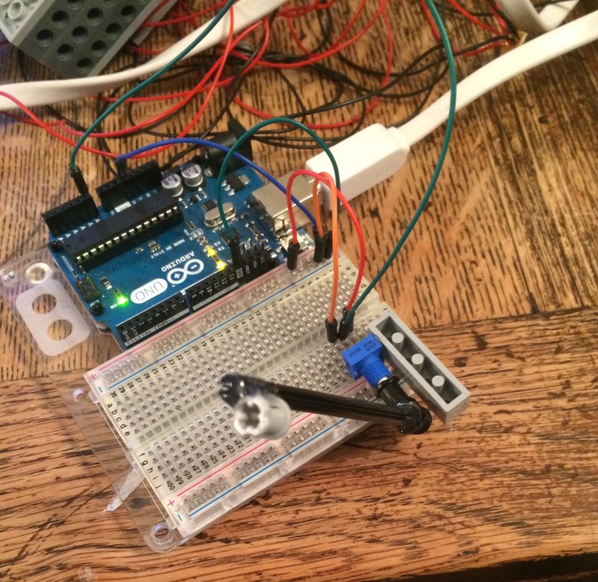
Because toneglow is fully wired, cabling is a large issue, and we wanted to make it so that it can easily be taken apart/put back together. In all of the prototype videos so far, the cables have been directly soldered to the control units on one end and just poked into the breadboard at the other end. This worked, but was obviously far from ideal as seen from this picture of a mess of wires:
This picture is from when there were no LEDs, so try to imagine 10 more cables going around all over the place precariously.
Ethernet Cables:
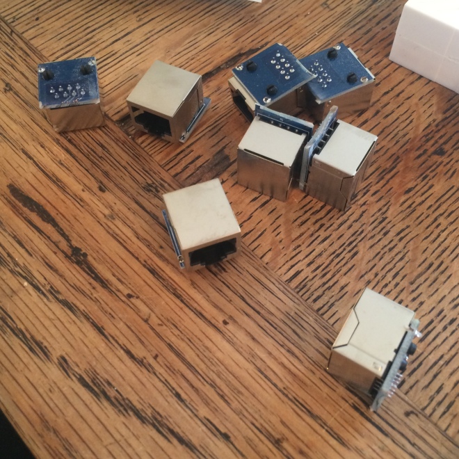
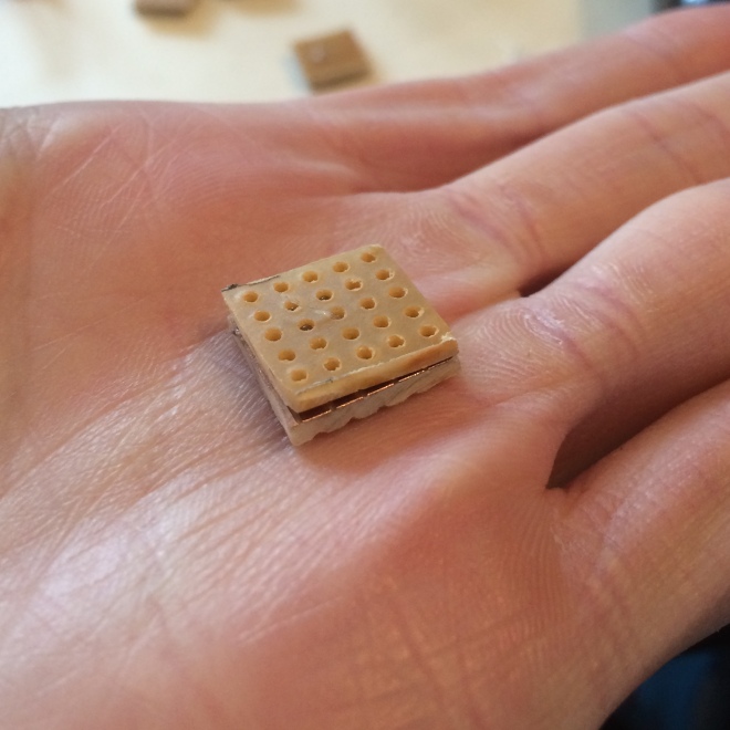
We were using ethernet cable to connect all of the units as it has 8 wires inside a reasonably slim frame. This gave us easy room to expand if we wanted to insert more components which would use more cores of the cable. Using ethernet cable was also useful as we could just solder ethernet sockets to the units and to the Arduino. But we realised quite soon that finding female ethernet sockets as a standalone item was quite difficult. We then decided to scour Amazon for ethernet couplers which we thought we could take apart and use the sockets from those. And this is what we came up with.
As the image shows, each coupler has a PCB with two female sockets attached to it. We tried to desolder them from the board but found it to be quite difficult as it was fiddly to get the solder sucker into all the crevices. After trying this for a while we decided just to go the old fashioned brute force way and use a dremel to cut them in half. We ended up with these:
They’re not pretty but they are functional.
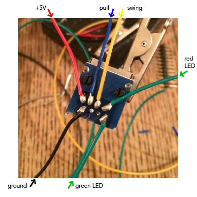
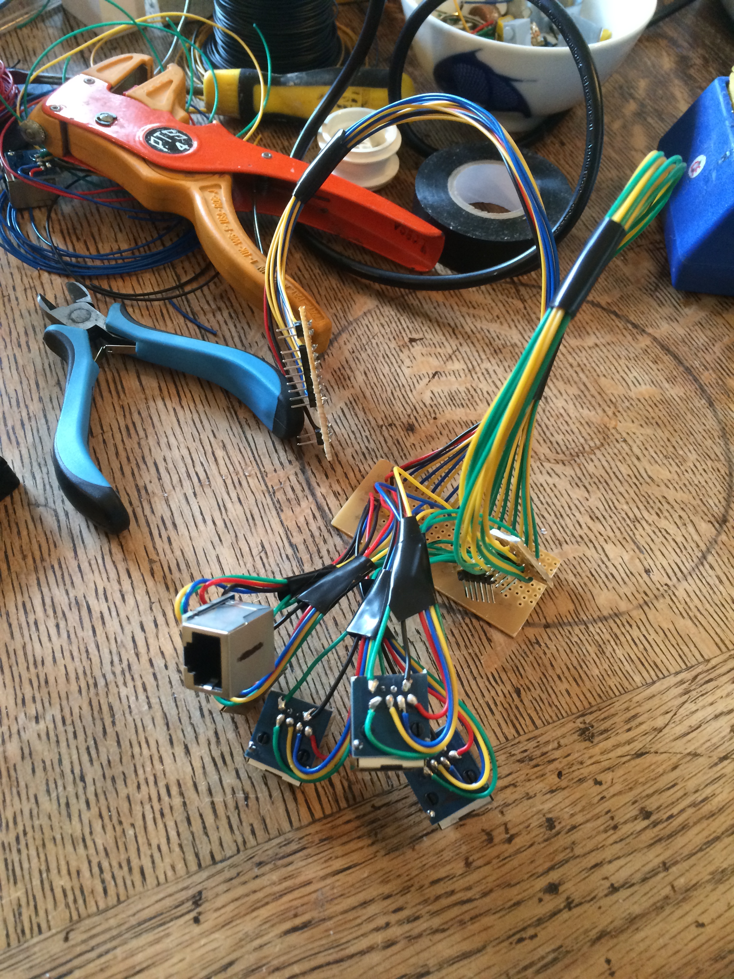
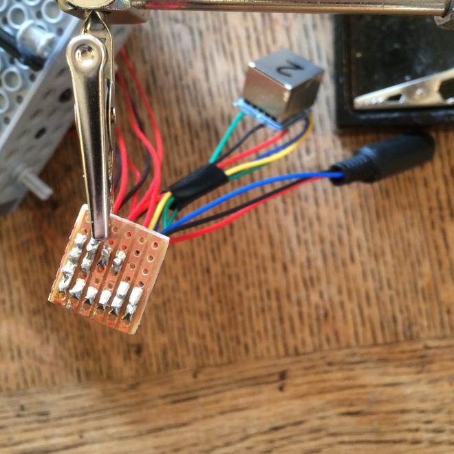
Having standardised connections made it a lot easier for us to do wiring, as we could work out which pins were what and just easily connect it that way. This is how we connected the pins:
As you can see the soldering was quite fiddly so it was hard not to get a short, but we managed it in the end and ultimately, the addition of these ethernet cables is what makes our project so much more easy to set up and take down.
As a side note, you will notice that the cables used for the LEDs are both green. The one for the red LED is marked at the other end though, so it can be easily differentiated.
Arduino Mock Shield:
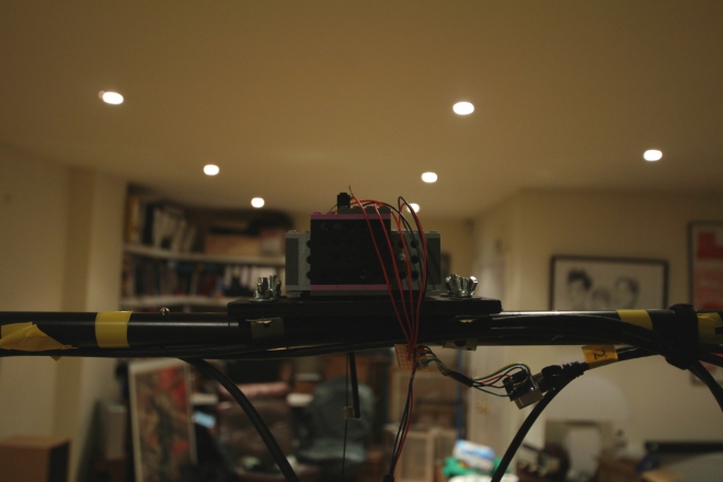
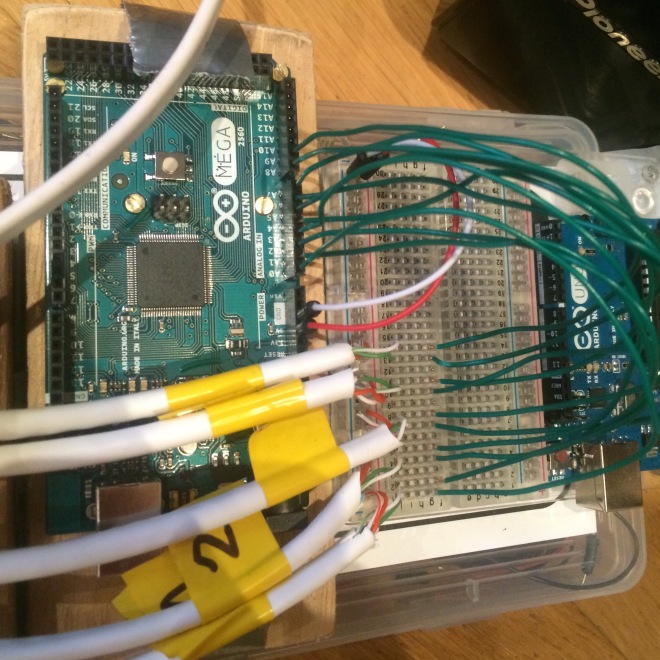
After building all of these ethernet connectors, we knew we needed to build a shield to incorporate all of the cables into the Arduino instead of plugging into a breadboard. So we did. Unfortunately we didn’t take any pictures during the building process, but it was quite simple as it was just connecting cables to one another. This is a picture of what it all looks like :
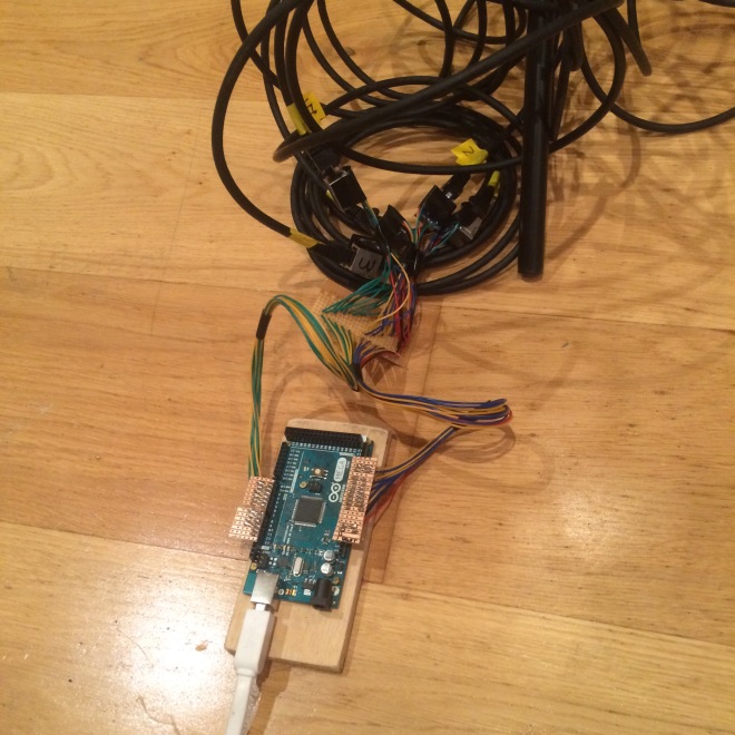
And when it is attached to the Arduino (with all the ethernet cables):
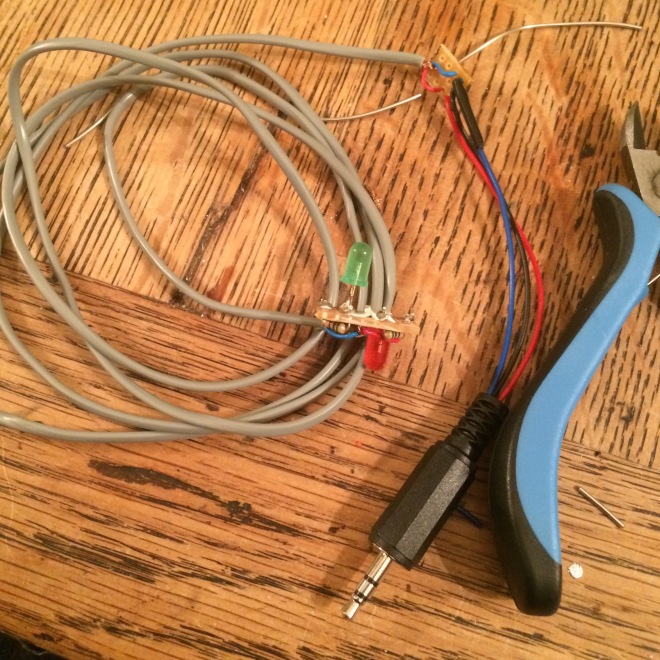
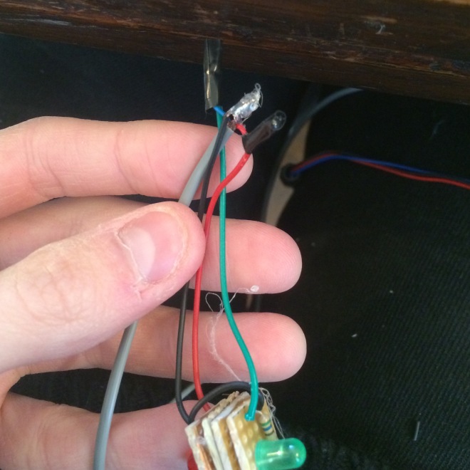
Brilliant, now we have an easy way of connection. Now the focus was back to the Lego units, and more importantly the balls. We wanted a way of being able to take the balls off the strings and also being able to disconnect them from the ethernet port on the Lego units themselves (see the last picture of this post to see how it all looks). We resolved this problem by using 3.5mm stereo plugs and sockets as they have three connectors and this was all we needed. We could also colour code the wire so it was easier to set up. Unfortunately though we ran out of green wire so the green LEDs actually use blue wire (a bit confusing but at least the ground was still black and the red LED used red wire).
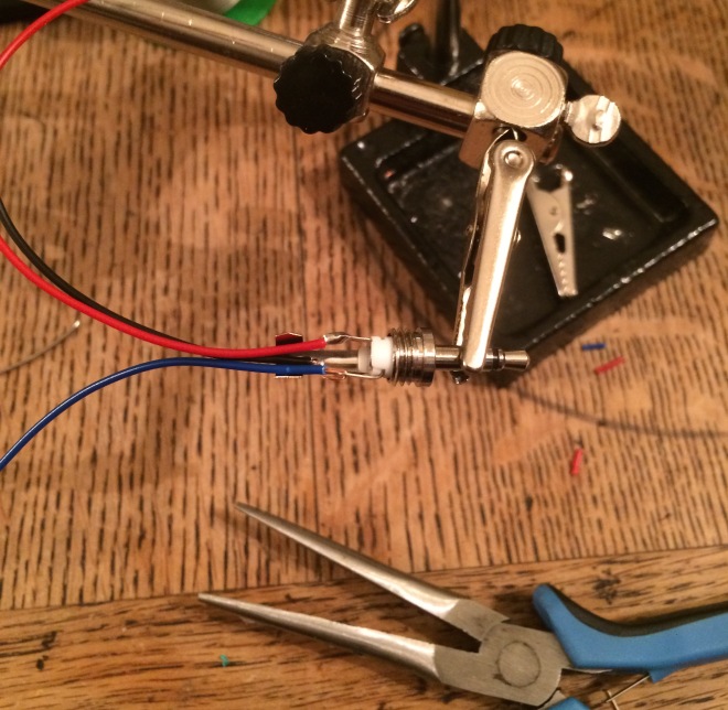
Here is a picture of soldering the plug.
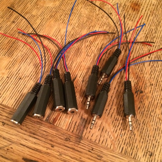
And here all of the plugs and sockets together:
If you are eagle eyed you will notice that there is one missing. This is because we made a prototype cable before to check if it worked, but it used a yellow instead of blue wire so it didn’t fit as well into the picture (colours are important you know?).
Here is it all assembled. Now, before getting into this picture we would like to clarify a few timeline issues. We actually made the cables at the same time as making the balls, but we wanted to keep all of the cabling issues inside one post to make it a bit nicer. You can tell that we did them at the same time as the balls because this picture if of the cable attached to one of the original light systems, rather than the new and improved version.
We also used a small piece of stripboard to attach the grey cable to the other component cables, because the grey cable was far to delicate to mount inside the plugs. In order for the solder to stick properly inside the plug, the metal of the plug itself had to be at a certain temperature. But this took some time as it is quite thick, and when the metal got to that temperature, it melted the cable which made it short with itself. Stripboard was much more efficient as it is very quick to get up to the right temperature.
Bringing Everything Together:
Now it was time to bring everything together at the string potentiometer end. This involved soldering the ethernet sockets to the potentiometers and also to the 3.5mm sockets. And this is what it looked like:
In the prototyping videos so far, the part which the user holds to interact with the system has been a series of cans. Obviously these won’t be in the final design. Instead we will be using clear plastic balls with LEDs inside them, which is where the ‘glow’ in toneglow comes from.
Wiring:
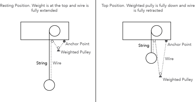
The major problem we have to face is how to wire the LEDs without interfering with the string system too much. The first thought we had was to use a system of pulleys with a wire so that when the ball is lifted the pulley goes down. Here is a diagram to further explain:
After trialling a mock up, we found that the pulley got in the way of the ball and was quite invasive on the space which people were using to move the ball up and down. It was also very difficult to find a three core wire (Ground, LED 1, LED 2) which would be flexible enough to work properly with a pulley.
We racked our brains for what seemed like an age, coming up with novel but ultimately ineffective ideas. Eventually we came up with the solution of just having the wire hanging freely and just be attached to the ball and the top of the string. This means that the wire doesn’t get in the way with any weights and can easily move where it needs to. We also think it makes the system look more natural and free as if there isn’t too much holding it.
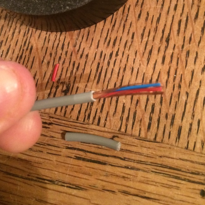
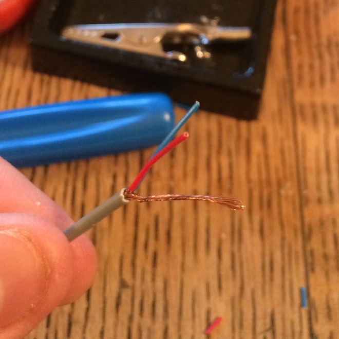
We found some wire at Maplin which seemed perfect for our needs. It is shielded audio cable which has two cores and a protective sheath of wire around them. We figured that we could collect and move the sheath to one side which would allow us to solder it to the board and use it as a ground. These images illustrate how the wire looked before and after:
The sheath was very easily separated and twisted into its own section.
This wire is very thin and flexible which is perfect for our needs as it hangs quite loosely in quite a nice fashion.
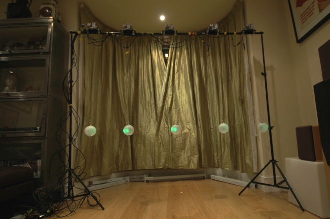
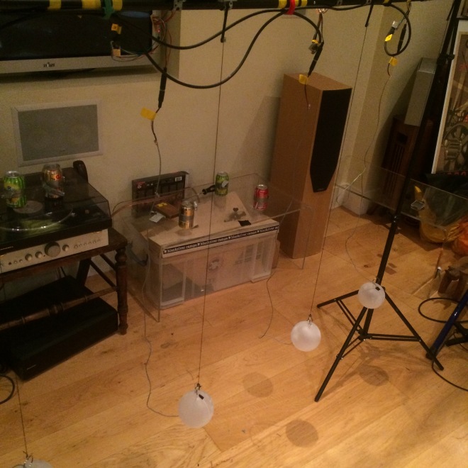
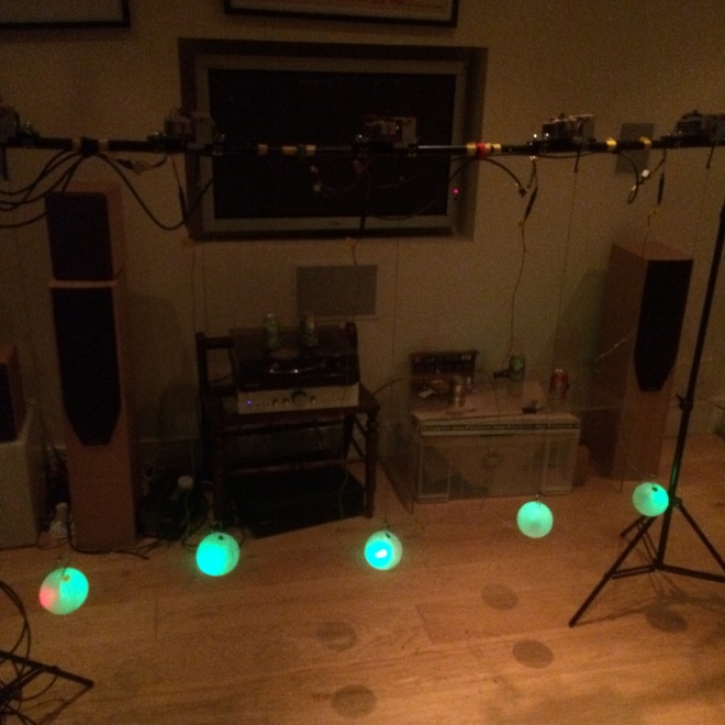
This is how the wire looks when it is hanging:
This is a picture of prototype 3 which is fully built. Its build will be covered in the next blog post, but you can see how the wire hangs.
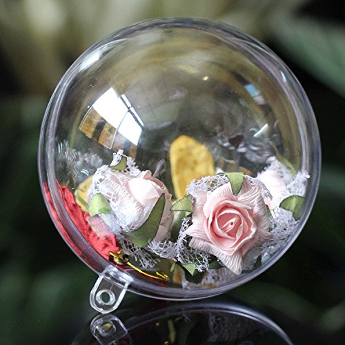
The Balls:
For the balls to use for the final installation, we ordered some transparent plastic Christmas baubles from amazon. They come in two halves so you can put whatever you want inside them. They look like this (minus the flowers and things):
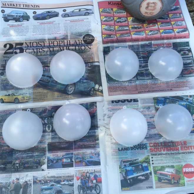
Initially we thought it would look quite nice if you could see the lights inside on the circuitboard. We thought it would look more ‘science-ey’, but we quickly realised it wouldn’t give us the type of diffusion we were looking for in the lighting. To remedy this, we bought some frosting spray paint which made the balls look like this:
After painting we realised that it was indeed a very good idea. The frosting gave a really nice texture to the plastic and was very effective at diffusing the light in the end. But that will be covered when we get to it.
The Lights:
The lights were unexpectedly difficult to produce due to the terrible mistake of building something without properly testing it (we learned to do proper thorough testing after this incident!)
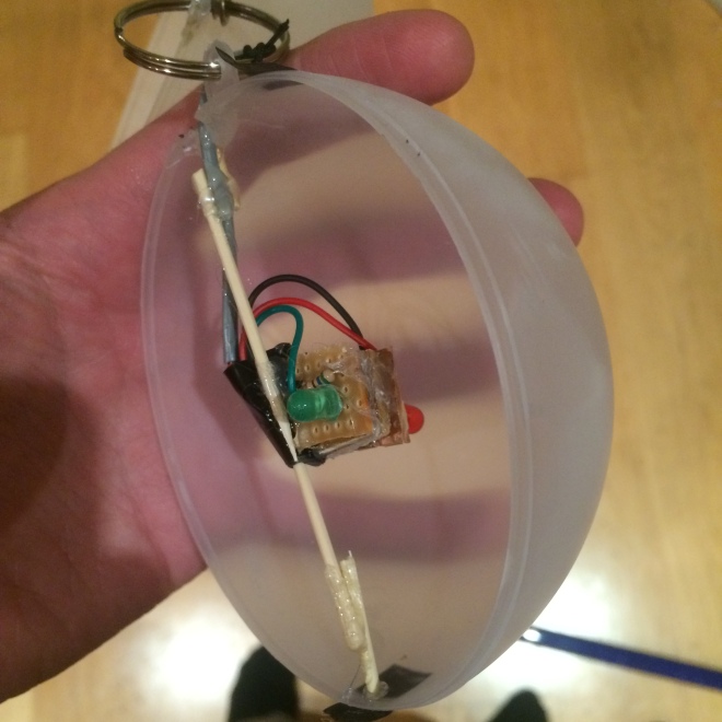
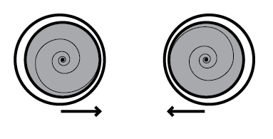
Essentially, we wanted two different coloured LEDs, of which one would react to the pulling up and down motion, and the other would react to the back and forth swinging motion. Each one would light up a different side of the ball so that the colours would be more obvious and linked to the movement of the ball.
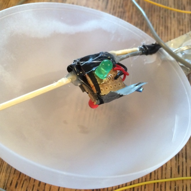
For the first iteration of the lights we decided to go for a very simple solution of soldering each light to its own breadboard and having a common ground between them. We forgot to take pictures during the building stage, but this image shows it quite simply:
The breadboards are taped back to back with some tape between them so they don’t short circuit. They are then glued with a small blob of hot glue to two toothpicks to be mounted into the inside of the ball, and a small notch was cut out of the ball with a dremel to allow the wire through. With some quick programming in Arduino this was the result of the first ball:
Here is the code for this ball, it includes the functions to control the LEDs. The values are smoothed because sometimes there are outliers in the sensor information and make the red LEDs flash in their resting position which they are not meant to do. The smoothing helps eliminate these values. We decided not to output the smoothed values to Max/MSP because it creates a bit of a delay in the sound when you move the balls around, and the outliers have a lot less of an effect on the sound. The up and down motion controls the brightness of the green LED and the back and forth motion controls the brightness of the red LED.
//This is the code for Prototype 2.5, the test for one ball with LEDs

const int one = A0;
const int two = A1;

int ledOne = 2;
int ledTwo = 3;

int brightness;
int bbrightness;
int brightnessOne;
int brightnessTwo;

//smoothing

/////////// smoothing A0 ///////////
const int numReadingsA0 = 10;
int readingsA0[numReadingsA0];
int readIndexA0 = 0;
int totalA0 = 0;
int averageA0 = 0;
//////////////////////////////////////

/////////// smoothing A1 ///////////
const int numReadingsA1 = 10;
int readingsA1[numReadingsA1];
int readIndexA1 = 0;
int totalA1 = 0;
int averageA1 = 0;
//////////////////////////////////////


void setup()
{
 Serial.begin(9600);

 // initialize all the readings to 0:
 /////////// smoothing A0 ///////////
 for (int thisReadingA0 = 0; thisReadingA0 < numReadingsA0; thisReadingA0++) {readingsA0[thisReadingA0] = 0;}

 /////////// smoothing A1 ///////////
 for (int thisReadingA1 = 0; thisReadingA1 < numReadingsA1; thisReadingA1++) {readingsA1[thisReadingA1] = 0;}


 pinMode(ledOne, OUTPUT);
 pinMode(ledTwo, OUTPUT);


}

void loop()
{

 /////////// smoothing A0 ///////////
 totalA0 = totalA0 - readingsA0[readIndexA0];
 readingsA0[readIndexA0] = analogRead(one);
 totalA0 = totalA0 + readingsA0[readIndexA0];
 readIndexA0 = readIndexA0 + 1;
 if (readIndexA0 >= numReadingsA0) {
 readIndexA0 = 0;
 }
 averageA0 = totalA0 / numReadingsA0;
 //////////////////////////////////////

 /////////// smoothing A1 ///////////
 totalA1 = totalA1 - readingsA1[readIndexA1];
 readingsA1[readIndexA1] = analogRead(two);
 totalA1 = totalA1 + readingsA1[readIndexA1];
 readIndexA1 = readIndexA1 + 1;
 if (readIndexA1 >= numReadingsA1) {
 readIndexA1 = 0;
 }
 averageA1 = totalA1 / numReadingsA1;
 //////////////////////////////////////


 brightness = averageA0;
 bbrightness = averageA1;

 // using the map function as a sort of calibration.
 // you have to input the minimum and maximum values of where you want the ball to be
 // and input it into the map function to give the desired outputs

 // brightness one is the red led and is controlled by swing, if it is pulled
 // towards you then it gets brighter

 // brightness two is controlled by the up/down motion. if the ball is raised the
 // green LED becomes dimmer
 brightnessOne = map(brightness, 470, 660, 0, 255);
 brightnessTwo = map(bbrightness, 285, 685, -255, 255);

//limit the brightness so it doesn't wrap if the map function goes over its limits
 if (brightnessOne > 244) {brightnessOne = 255;}
 if (brightnessOne < 1 ) {brightnessOne = 0 ;}
 if (brightnessTwo > 244) {brightnessTwo = 255;}
 if (brightnessTwo < 1 ) {brightnessTwo = 0 ;}

 analogWrite(ledOne, brightnessOne);
 analogWrite(ledTwo, brightnessTwo);


 Serial.print(analogRead(one));
 Serial.print(",");
 Serial.println(analogRead(two));

}
Here is a very quick video explaining the Maxpatch behind it.
It works! Now it’s tome to build some more.
And this is where the fatal mistake happened…
We decided to do the drastic deed of redesigning the circuit without making a prototype and making all five at once.
We decided to mount the two lights to one board and have a common ground on one board and the two control wires going to each side. This is it looked like:
The stripboard was cut in the right places at the back so the circuit didn’t short (or so we thought) and after mounting this is what it looked like:
As mentioned earlier, we made and tested 5 of these without testing properly. We tested whether each light came on but we didn’t test whether they would both come on at the same time.
After all that time building and gluing we became quite angry so did not take a video of it not working properly, but the problem was that only the red light was illuminating, even when both were connected to power, which was down to bad circuit design. We checked the stripboards over and over again for shorts and bad design elements but we could not for the life of us figure out what was going wrong. Time was becoming short before we had to present it to the public so we decided to go back to the slightly uglier prototype method, but we figured that because the lights would be inside the balls, then no one would see the ugliness which lay below.
The Lights Mark 2 (But really back to the prototype):
So, after running out of time (and components) we decided to recycle and rebuild. Like mentioned before, we went back to the original design but tweaked it slightly to make it more rugged.
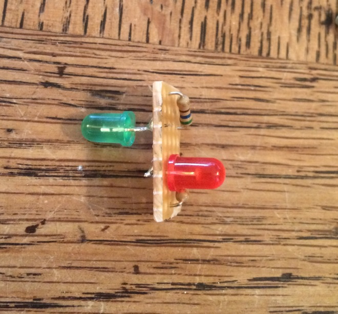
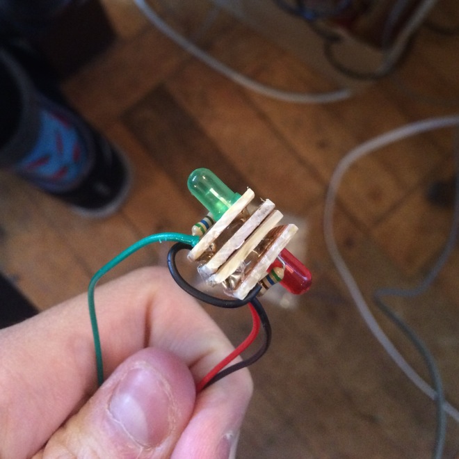
Here is an exploded view of what the final lights look like:
This is before the wires were cut but we tested and tested to make sure these worked and they did!
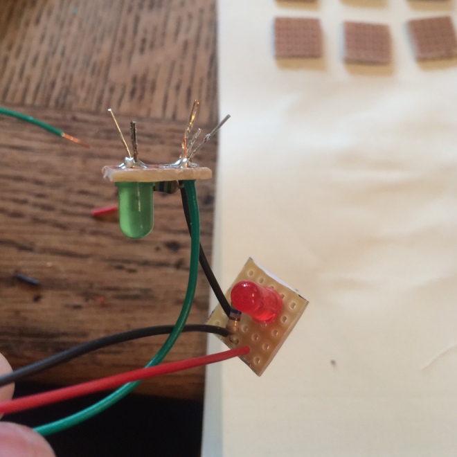
Instead of putting tape between the two breadboards, we decided to put more breadboards. We didnt want to risk one of the sharp solder joints poking through to the other board and short circuiting it so we created these little back to back glued stripboard parts to put in between:
There’s no risk of shorting here any more.
Heres what they looked like when glued between the LED boards:
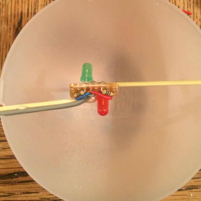
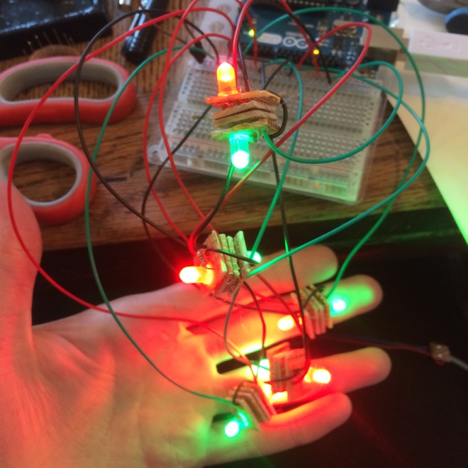
They are a fair bit larger than the other version, but they are solid and they work properly as seen in this picture:
I don’t think anyone has been as emotional as we were seeing them all work in harmony. But now it was time to mount them inside the balls.
As a side note, you may have noticed that we didn’t solder the grey wire directly to the stripboard. This was because its quite delicate and has an unguarded ground, so we didn’t want to stretch it out too much over the two stripboards in fear of shorts and wires being cut. So instead we soldered the grey wire to the patch wires poking out and covered the ends in hot glue and tape:
We then folded the wire over and glued it to the side of the board and to the toothpicks inside the balls. We decided to cut the existing toothpicks in half and just mount them to those to not risk breaking the balls. The inside final product looked like this:
They work! You will have to wait until the final video to see them all working in harmony, but this picture shows them all being illuminated:
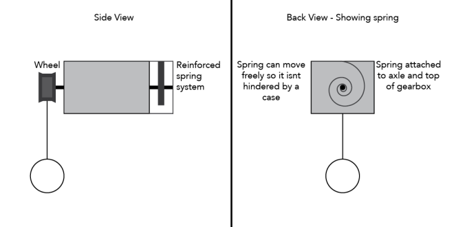
We thought of the idea to be able to mount the spring system to one side of the gearbox and the string part to the other side. This means that the spring part can be enclosed and properly reinforced on the top and bottom, while the string part can move freely.
In the first version the glue got stuck on the wheel and made it unstable. It was also quite delicate as the spring came unattached quite easily, and if this happened it was a real pain to get it back. It also wiggled around a lot due to the spring pushing out and the wheel not being properly centred as explained in a previous blog post.
This is the initial sketch of how it will work.
This diagram shows the Mk i version of the new spring system. The spring became too hard to turn too quickly when it was connected to the axle which the wheel is connected to. This was also a problem we faced when the retractable key rings were mounted directly to the axle with glue. In order to remedy this, the spring was attached to the second axle along, which is one step down in gearing within the gearbox. This meant that it would be turned a lot less frequently with more turns of the wheel. It also gave it less power to retract which was perfect for us as we only wanted the string to retract as it was pulled up.
After tweaking and moving the spring to the second axle this is what it looks like
This gives the perfect amount of tension in the spring while still having enough strength to retract, but makes it very smooth and easy to be able to pull the string, which means that not that much weight will be needed in order to pull it down. It was an unexpected advantage of the Lego being able to attach a spring to the second point of the gearbox. In any other gearing system, it would’ve been more challenging to access this space, and could potentially not be possible, but with the modular nature of Lego it was incredibly easy. It also went to prove further that Lego is an incredibly good tool for prototyping as there are no destructive ways of moving components around.
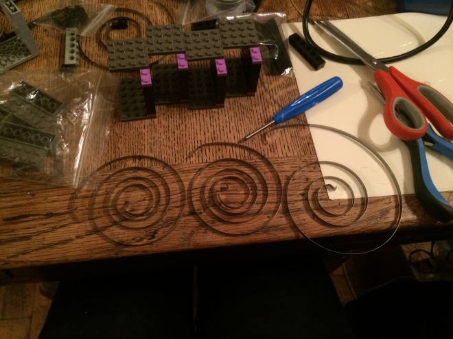
Initially we were worried because all of the springs seemed to have different tensions as shown in this image:
We thought that because of this that the action would be uneven between the balls, but it ended up being perfectly fine.
Earlier we mentioned that now we don’t need as much weight to pull the string down. This was an issue because the balls which will house the LEDs are not very heavy, and adding weight to them would cover some of the surfaces so that light would not diffuse properly.
Initially we had cans hanging from the strings, they were quite heavy but were the required weight to pull the old strings down enough due to the higher tensions in the springs. The weight of all of the cans put quite a strain on the bar and also made it quite unstable when it was fully extended upwards. In the previous video, you can see that the bar was around head height, which is not ideal for this system as it can obscure the vision of the user. With this new system, we can fully extend the bar upwards and make sure that the string potentiometers are out of the way of the system, which makes for a more immersive experience.
In this video you can see a before and after of the action and how much it is improved.
After building the first string potentiometer system, we went on to build 4 more to increase the user interaction and to be able to get more people to be able to use the system.
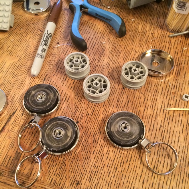
The first problem we had to tackle was that when there is no protective face on the side of the spring of the keyrings, the spring has a tendency to eject itself from the housing once pulled, like this:
We decided to glue a small plastic cover over the top in order to keep it inside and then glue the lego wheel over the top, this caused its own problems which will be elaborated upon later:
The building process for the new controllers is very similar to that of the first, so some steps have been skipped in order to make this post a bit more concise. Here are some pictures of the multiple pieces being constructed
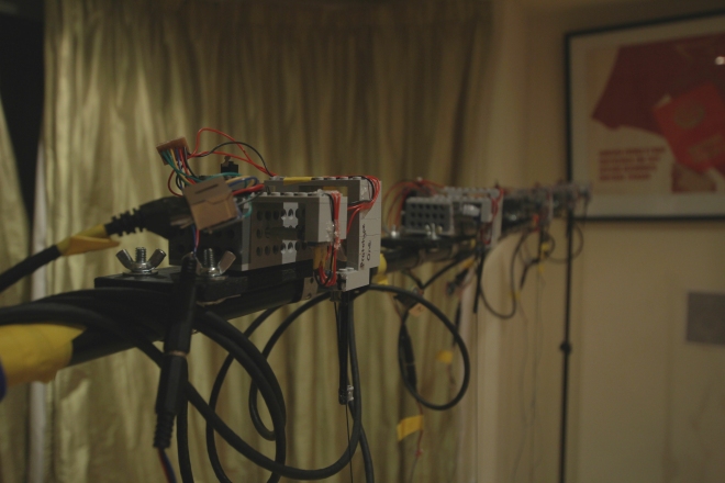
Here is a picture of all of the new controllers mounted to the bar.
This is a video of it in action!
One of the major problems we encountered with this was that the keyrings are not very smooth in their rotation, and it was incredibly hard to align the lego wheel with the centre of rotation, as the spindle with the string on it did not really stay centred through its rotation. Becuase of this, it moves around quite a lot, which ends up moving the Lego pieces and eventually making them come loose and falling off the top. Most of the pieces are glued together to prevent this, but we wanted to keep the keyring side of it modular so we don’t have to change the whole gearbox if we want to change the system. The system works fine for a prototype, but we need to make it more tough if it is going to withstand the constant use from people moving it around, it needs to be virtually bombproof so that people who don’t necessarily know how delicate it is can use it without us having the fear of it breaking.
Glueing the Plastic cover and Lego wheel to the internal unit worked, but the main and most irritating problem was that if this part came away from the metal housing (which was incredibly easy for it to do) the spring would unravel and be incredibly hard to reattach to the spindle. This is the main feature which needs to be improved, the ability to fix it easily if it breaks.
We are going to start thinking about a way to create a more stable implementation for this system, keeping it more centred.
Building multiple controllers came with a new set of problems which boiled down to two major parts: keeping consistency and routing and keeping a handle on wires. Originally, the first prototype used 4 individual wires taped together going straight into a breadboard, which worked fine, but was a bit fiddly. Multiplying these wires by a factor of 5 exponentially increased the confusion of wires going into the breadboard and reliability of connection due to some wires unexpectedly pushing on each other and coming loose. We decided that instead of using individual wires that we would use ethernet cable. Ethernet cable has 8 cores, so plenty for each unit, even if we wanted to expand functionality (for example, adding LEDs ) then we could just use more of the wires inside the cable. The flaw of ethernet cable though is that it is quite stiff, so it is hard to plug into a breadboard for testing. Eventually we will make astripboard unit which can take all of the inputs and spread them out properly, and be properly housed with connectors for easily plugin into the Arduino. At the minute the cables are hardwired to each module so if we did this it would meanthat they will all be connected together and just create a massive tangle of cables. We thereore need to make some plugs which we can remove easily from each module, and also to the Arduino. We will probably use ethernet plugs (as it is ethernet cable) so they can easily be clipped together and apart.
Fritzing Diagram:
Code:
This code is fairly simple as it just reads values and outputs them to Max/MSP.
//This is the code for Prototype 2 with five cans

const int one = A0;
const int two = A1;
const int three = A2;
const int four = A3;
const int five = A4;
const int six = A5;
const int seven = A6;
const int eight = A7;
const int nine = A8;
const int ten = A9;


void setup()
{
 Serial.begin(9600);
}

void loop()
{
 // output analog values as serial data to be read by Max
 Serial.print(analogRead(one));
 Serial.print(",");
 Serial.print(analogRead(two));
 Serial.print(",");
 Serial.print(analogRead(three));
 Serial.print(",");
 Serial.print(analogRead(four));
 Serial.print(",");
 Serial.print(analogRead(five));
 Serial.print(",");
 Serial.print(analogRead(six));
 Serial.print(",");
 Serial.print(analogRead(seven));
 Serial.print(",");
 Serial.print(analogRead(eight));
 Serial.print(",");
 Serial.print(analogRead(nine));
 Serial.print(",");
 Serial.println(analogRead(ten));
}
Max Video:
Here is a video describing the maxpatch for this protytpe. In this video I also describe the problem of ambiguity in sound, especially when there are 5 controllers in use, and also the way it has been overcome.
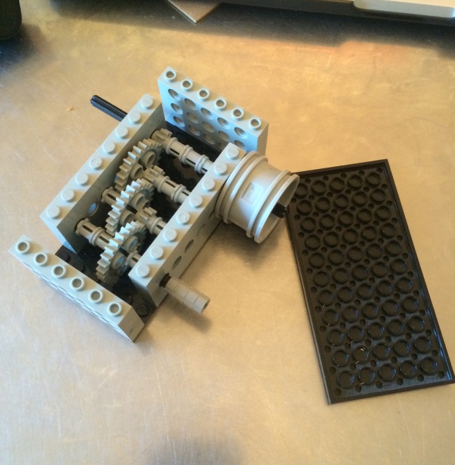
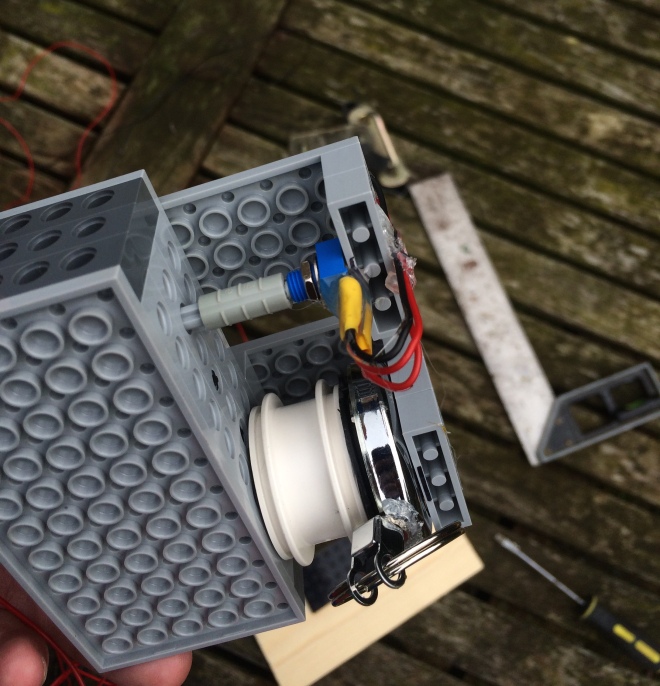
For the string potentiometer we wanted to use a Lego gearbox to map the many turns of a retractable keyring to a small enough amount to turn the potentiometer.
So we made this:
It is a very simple sequence of gears which all have a ratio of 1:3, therefore the final ratio is 1:9, so one full turn of one side will turn the other side 9 times. This therefore means that I will need 6.75 turns of the lower geared side to turn a potentiometer through its whole 270 degree sweep.
Skip forwards a bit (because we forgot to take pictures) to this:
This is a lego wheel glued to a retractable keyring on one side so that it turns the wheel, and a potentiometer glued via a lego gearbox to a potentiometer on the other side. The whole range of the keyring only turns the potentiometer about a quarter of a turn. In the final versions, there will probably be a longer range for the string to travel so the potentiometer will turn more. The wire connections are covered in hot glue to prevent shorts and create some stress relief.
This is the part which the string goes through, it measures the tilt of the string via a potentiometer and can send the information to the Arduino.
If you’re reading this after our introduction, you will have noticed that we mentioned the use of distance sensors for the back/forth motion. The reason we didn’t go with these in the end was because there is no guarantee that they would always be facing the wall as they might spin around, and we also didn’t want to limit our project to only being installed next to a wall. The surface of the wall would also have a marked effect on the reaction of the sensor, for example, if it was glossy it wouldn’t give accurate feedback. Due to these shortcomings of distance sensors, we decided that this physical string tilt system would be the best for our needs.
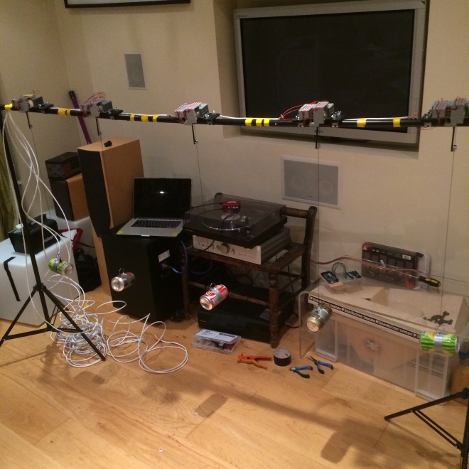
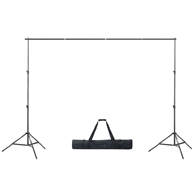
It will be mounted to a green screen stand like this:
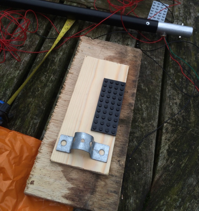
It is essentially a bar mounted to two tripods, so we needed to figure a way to mount the lego to it. We glued a Lego plate to a piece of wood which has metal mounting points.
This is the first metal mount which is moulded to the pipe size.
Here is a picture of bending the metal in a vice
We drilled a few holes to mount a nut and bolt to the metal parts, these can easily be tightened to clamp on to the bar. I am going to put wing nuts on it to make it easier to tighten and remove.
Here it is mounted to the bar, you can see the string is routed through the lego axle. The wire is hot glued to the lego to keep it secure and provide strain relief.
Heres a closer up picture of the routing. The metal part is there so the string doesn’t fly back up into the retractable keyring. This happened once and it took a long time to fish it back out.
One of the problems faced with the mark One version is that I wanted to make it easy to dismantle and reattach so it is more portable. But the string potentiometer section is fairly fragile and can easily come apart, the spring can come unattached if you pull the side part off. Also it moves around quite a lot as it was hard to mount the wheel perfectly centrally on the keyring, and also the tension of the spring always pushes the wheel to one side so it pushes out as it is rotated, as in this diagram.
The spring pushes from central point outwards. Because the internal wheel of the keyring which holds the spring and string is connected to a wheel which had a hole in the middle which was slightly bigger than the spindle it was attached to, it didn’t remain centred and was always pushed out from the centre in some direction
Here is a video of it in action
Fritzing Diagram:
The actual circuit for the first prototype is incredibly simple once its shrunk down. Essentially the final version of this just has extended wires going to the gearboxes.
Code:
This is the code for the first prototype, it is incredibly simple as it just needs to take the potentiometer values and spit them out through the serial port into Max.
//This is the code for Prototype 1 with one can

const int one = A0;
const int two = A1;

void setup()
{
 Serial.begin(9600);
}

void loop()
{
 Serial.print(analogRead(one));
 Serial.print(",");
 Serial.println(analogRead(two));

}
Max Video:
Here is a quick video overviewing how the Maxpatch works:
For one part of the control of our project we need to use string potentiometers. They are basically an automatically retracting string or wire connected via a gearbox to a potentiometer in a box. When the string is pulled, it outputs a value of resistance depending on the string position. These are fairly specialised components which are used primarily in robotics to measure distance covered by arms or other things.
As you can see in this image, the wire is connected to an arm and it can measure the distance.
So we went researching where to get these devices and found it was quite difficult to obtain them without buying wholesale. We eventually found one which we thought suited our needs
Perfect! Low cost and small enough. It also had a useable range for our project. We proceeded to try to find where to purchase them from and to receive pricing information.
I’m sorry could you repeat that please?
Hmm, so, in the famous words of the internet:
This didn’t seem so ideal any more, especially as we potentially need 5 or more of these things. So we went back to researching and came up with nothing. There are cheaper ones out there but they are still ridiculously expensive.
So back to the drawing board.
We was as home and had a brainwave to use retractable keyrings. They have a string and they retract. And most importantly, theyre cheap and easy to get hold of.
Hmm 4 stars, its a gamble. But we are men who live life on the ragged edge so we went balls to the wall and ordered a bunch.
But now for problem number 2. How could the long range (and many rotations of the internal wheel) be converted into a useable distance for our project? And how could the low power of the keyring’s spring be turned into something with more torque?
The next idea was born. Lego. We proceeded to create a gearbox out of lego which turned the large motion and many rotations of a keyring into a smaller and useable distance (3/4 of a turn ideally). Lego is cheap and easy to build. And while it may not be ideal for industrial robotics, it proved to be useable for this project.
In the next post we’re going to show the building process of the lego parts.
toneglow is a project which will use the close integration of Physical Computing and Max/MSP to create an immersive interactive environment installed into any space. We aim to help people create music in groups. People who have never met will be able to play music together in an incredibly interactive way.
We are creating toneglow because we want to use interactive technology to bring people together and have the potential to develop a sense of unity amongst strangers. We want it to be highly useable by anyone no matter what their musical or technological experience is, and bring the ability to create music to anyone and everyone. We feel that a strong correlation between physical movements, light and sound is essential to the instant gratification of people using the system, and also will create more of a sense of fulfillment after its use. Essentially, we want people to walk away from toneglow wanting to tell people about it and feel accomplished with what they have created.
We are primarily aiming toneglow at people with less musical experience so they can create something without having to know the process behind it. As a side goal, we also want to spark an interest in people into the world of Physical Computing and music creation, and general computing beyond the everyday commercial use.
There will be a series of ‘pods’ which will be hollow translucent plastic balls containing a number of LEDs whose brightness or colour (if they are RGB) will be controlled by distance sensors and string potentiometers mounted inside. We will probably have two sets of different coloured LEDs inside, one sets brightness being manipulated from X axis control and one from Y axis control. As stated earlier, there is the possibility to use RGB LEDs to eliminate clutter inside the pods. The pods will be translucent so that the light is diffused more evenly and the so that the user won’t be able to see the internal circuitry. A small hole will be cut in the back of the pods so that the distance sensors will be facing the wall behind, and the pods will be hanging at the bottom of the throw of the string potentiometer from the ceiling about 30-40cm from the wall. There is also the potential for us to use distance sensors facing upwards on the pods as well as towards the wall so there is a slightly different type of X/Y control, but we could be limited by how high ceilings are in the rooms. Conversely there is the potential to mount string potentiometers onto the back of the pods instead of distance sensors, but we feel that this might make too much visual distraction with the number of strings coming out. Prototyping and experimentation will help us decide which is the best system to use. As the user moves the pod around, the distance sensor and string potentiometer will give different values and in turn will manipulate the sound. The sound produced from each pod will be different so the user can recognise what they are controlling, but the sound will interact with the other pods’ tones in a musical way. We aim to build around 6-8 pods, possibly more. If we created more, we would use multiplexing with the Arduino to get more inputs and outputs.
The information from each pod will be sent through Arduino to Max/MSP, using the serial port, to create an ambient musical sound, for which the movement of each pod will have a direct effect. The light produced by each pod will also be in direct correlation with the sound created by it. We want to assign each pod its own speaker which will be in close proximity so that the user will have a more definite connection to the music which they are creating.
Inputs
-Distance Sensor from each pod (ultrasonic or IR depending on tests)
-String Potentiometer from each pod (potentially distance sensors too depending on tests)
Outputs
-LEDs in each pod
-Serial Output to Max/MSP which produces sound -Speakers from computer
Housing
Translucent Plastic ball which contains distance sensor, LEDs and string potentiometer, wired to the Arduino at a central point. It will be held by people who want to create music so will be sturdy enough to be able to withstand this.
Presentation
We will create a short video demonstrating the use of toneglow and how people interact with it.


